
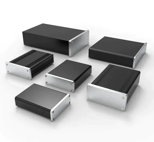
An amplifier that runs acceptably on an open bench may behave differently after its PCB, power supply, and cables are installed in a closed chassis. For professional audio hardware teams, the enclosure decision must address where heat is produced, which surfaces it can reach, and how the installed product releases it.
Design heat dissipation for an aluminum amplifier chassis by mapping component losses, establishing a realistic heat path, comparing cooling arrangements, and testing a representative assembly. Aluminum is only part of that system. The selected structure and interfaces must support the intended operating conditions; substantial-looking panels and numerous vent holes alone do not establish thermal performance.
What Heat Load Should the Chassis Design Address?
Start with heat generated inside the amplifier under defined conditions, rather than treating rated audio output as the chassis heat load. Class-D efficiency does not eliminate thermal design: TI's TAS5805M guidance discusses power-stage losses, operating settings, and PCB layout as separate influences. 1
| Input | Information to prepare | Design decision supported |
|---|---|---|
| Heat sources | Device and power-supply locations, estimated losses | Where cooling interfaces may be needed |
| Operating case | Supply, load, channels driven, signal, and duration | Which conditions the sample must represent |
| Installation | Desktop, cabinet, or rack placement and clearances | Available cooling space and access |
| Temperature criteria | Component limits and applicable product requirements | Acceptance criteria for engineering validation |
- Separate output from loss. Ask the electronics team for losses associated with the operating cases under review. Avoid selecting an enclosure from the amplifier's advertised output rating alone.
- Include other heat sources. Identify the power supply, regulators, and other relevant components rather than reviewing only the output stage.
- Distinguish estimates from evidence. Mark preliminary inputs and update them when device information or measurements become available. Do not let an early estimate silently become an approved requirement.
Statement: Rated audio output power alone defines the heat load that the chassis must dissipate.
Answer: False
Explanation: The thermal design needs the losses generated within the product under the specified operating conditions.
How Should Heat Travel From the Devices to the Chassis?
Identify the cooling route appropriate to each device package. Some designs transfer heat through a mounting tab or cooling surface; others depend substantially on the PCB. TI explains that package, board, and ambient paths interact, so a datasheet junction-to-ambient value is not automatically a model of your installed chassis. 2
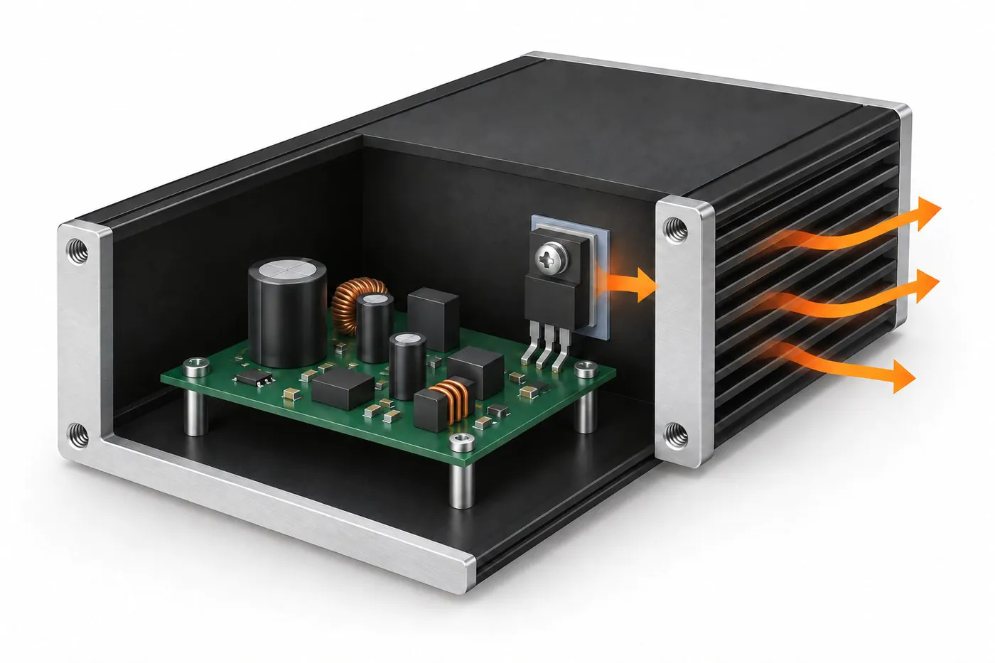
Conceptual illustration of a device-to-wall heat path; the correct route depends on the device package.
- Follow the device guidance. Identify the intended cooling surface and relevant package limitations before specifying contact with the enclosure.
- Document each physical connection. Show the device, interface material, contact land, and fastening arrangement on the mechanical design. Mere proximity to an aluminum wall does not define contact.
- Review separated parts. If heat must cross an added bracket or panel joint, include that interface in the review rather than treating the enclosure as one continuous part.
- Separate temperature locations. Do not treat an outer panel reading as the semiconductor junction temperature. Define the evidence needed for each component and surface criterion.
Statement: Every amplifier IC should be cooled by pressing its top surface against the chassis.
Answer: False
Explanation: The appropriate cooling route depends on the package and system design; the device documentation must guide the interface.
When Are Passive Fins or Fan-Assisted Cooling Appropriate?
Compare the available structure and installation space against the thermal requirement. Heat-sink performance depends on cooling conditions, including airflow and orientation; a natural-convection rating should not be transferred to another arrangement without reviewing its assumptions. 3
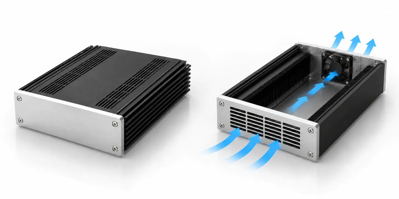
Conceptual cooling arrangements for comparison; performance must be validated in the intended installation.
- Identify the cooling air. Record whether the product uses room air, cabinet air, or air influenced by neighboring equipment.
- Review the complete passage. In a fan-assisted concept, check the intake, internal obstructions, outlet, and actual fan operating conditions together. Do not base approval on the presence of a fan alone.
- Include acoustic requirements. Professional audio products may impose noise constraints. The electronics and mechanical teams should evaluate cooling and acoustic acceptance together.
- Check service conditions. Determine which access, cleaning, or fan-related conditions belong in the customer validation plan. Avoid assuming that an open-bench result represents every installation.
Statement: A heat sink's cooling performance is independent of its installation and airflow.
Answer: False
Explanation: Cooling conditions are part of the performance specification and must match the configuration being evaluated.
What Must Be Specified at the Thermal Interface?
Define the contact geometry, interface material, and mounting conditions as a coordinated design. Boyd identifies surface condition, flatness, pressure, contact area, and interface thickness among the factors affecting interface resistance. 3
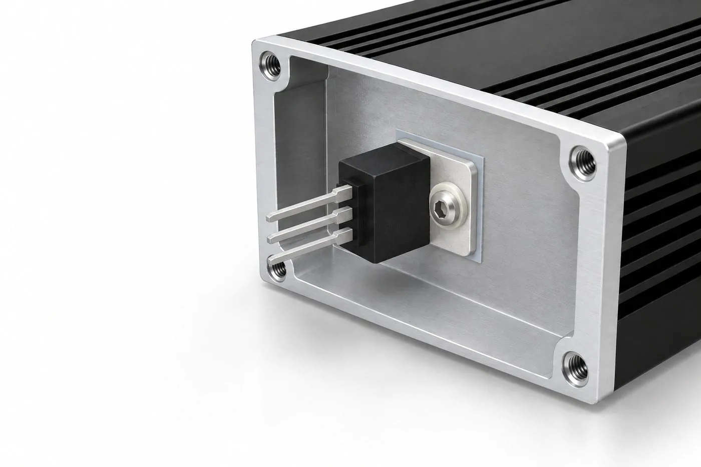
Conceptual interface detail; confirm the mounting arrangement against the device and material specifications.
- Define the assembled gap. Review the actual stack of parts and relevant tolerances before choosing an interface material. Do not specify a pad from its advertised conductivity alone.
- Confirm electrical isolation. The electronics team should establish any isolation requirement and verify that the material and hardware meet it; thermal contact does not settle electrical safety.
- Specify fastening requirements. Use device and material guidance to establish the mounting arrangement. Do not invent a universal torque or compression percentage.
- Control the contact-surface finish. Identify the required condition of the interface separately from visible cosmetic surfaces. Any masking or local machining needs an explicit drawing requirement and project review.
For a closer review of gap definition and contact geometry, see the thermal pad interface design guide.
Statement: A thermal-interface specification should include more than the material's conductivity.
Answer: True
Explanation: Geometry, contact conditions, fastening, and any electrical isolation requirements also need to be defined.
Which Chassis Features Should Be Reviewed Before Machining?
Review the functional layout before releasing cutouts, contact lands, or mounting details. Existing amplifier enclosure designs are worth evaluating when their structure fits, but their geometry and supply conditions still need confirmation.
| Feature | Check before release | Information to record |
|---|---|---|
| Profile or body | PCB envelope and usable cooling interfaces | Selected structure and applicable dimensions |
| Contact land | Device location and mounting access | Geometry and agreed acceptance requirements |
| Openings | Connectors, vents, and adjacent features | Positions, edge conditions, and relevant constraints |
| Finish and marking | Functional surfaces and visible panels | Finish specification and artwork revision |
- Start with compatible geometry. An existing extrusion may support customization through length selection and machining. Its width, height, or internal features cannot necessarily be changed without another profile or manufacturing route.
- Specify critical features deliberately. Agree on tolerances for the features that control fit and contact. No single machining tolerance belongs on every amplifier chassis by default.
- Keep routes distinct. Extruded components and CNC-machined housings require different manufacturing assessments. Do not promise the same material or process combination for all designs.
Statement: Reusing an existing extrusion means every chassis dimension can be changed without new tooling.
Answer: False
Explanation: Adaptation is constrained by the selected profile; a cross-section mismatch may require a different manufacturing solution.
How Should the Customer Validate the Thermal Design?
Test a representative assembled product against documented acceptance criteria. Record the configuration and operating conditions so that results support a specific engineering decision rather than a general claim that the enclosure has passed.
| Validation item | Record for the test | Reason for keeping the record |
|---|---|---|
| Configuration | Chassis revision, electronics, interface, finish | Identify what was actually evaluated |
| Operation | Signal, load, supply, channels, duration | Make the operating case reproducible |
| Installation | Covers, orientation, clearances, neighboring equipment | Avoid relying solely on an open-bench result |
| Observations | Measurement locations, method, temperatures, behavior | Compare evidence with the defined criteria |
- Close the intended enclosure. Include the relevant covers, cables, and mounting conditions in the customer test configuration.
- Use suitable measurement methods. Document sensor placement and method limitations. A thermal image alone does not establish junction temperature or every acceptance requirement.
- Record revisions and repeat affected checks. If a vent, interface, component, or finish changes, assess which earlier conclusions remain applicable.
PUMAYCASE provides enclosure manufacturing and customization support. The customer remains responsible for electronics installation and complete-product validation; PCB installation, wiring, and box-build are not supplied services.
What Should Be Approved Before Repeat Production?
Release the enclosure against a controlled mechanical configuration and the customer's completed review. Carry forward the requirements that matter to fit and cooling without presenting the enclosure supplier as responsible for the amplifier's complete thermal design.
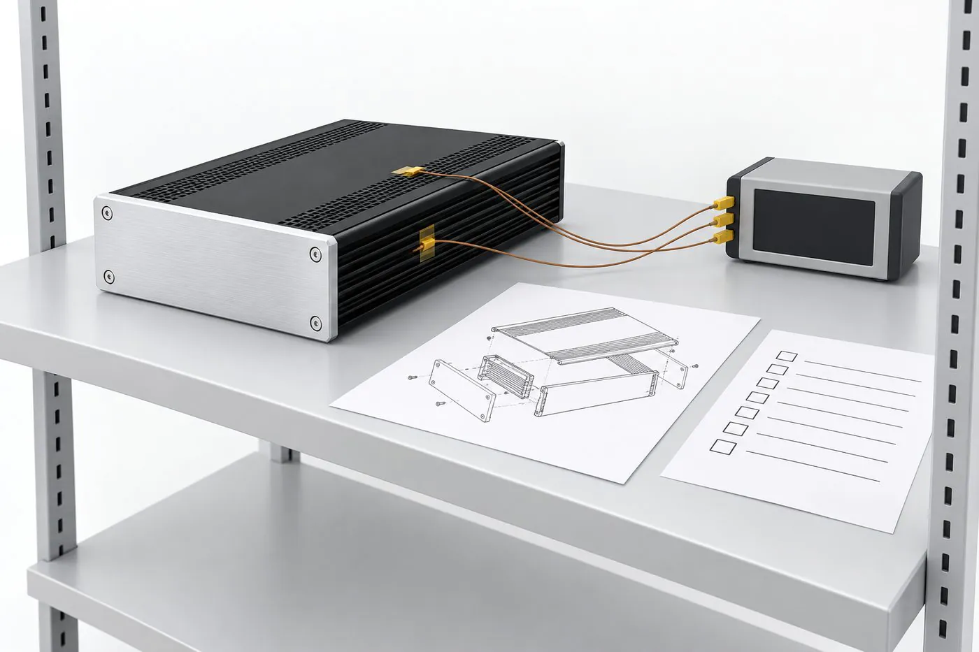
Illustrative review setup only; no measured result or test facility is represented.
- Freeze the relevant files. Identify drawings, interface requirements, finish notes, and approved deviations.
- Agree on part acceptance. Specify which mechanical and appearance checks are needed for supply. Keep these distinct from customer system tests.
- Flag changes before reordering. New output devices, PCB layouts, or mounting details may require renewed engineering review even when the exterior appearance is unchanged.
Use the approved configuration to coordinate samples, production, and later repeat orders; quantities and delivery conditions remain project-specific.
Conclusion
Design heat dissipation for an aluminum amplifier chassis around documented losses, a defined device-to-environment path, suitable cooling geometry, and customer validation in the intended installation. Confirm interfaces and machining requirements before approving the enclosure for production. Share your PCB envelope, heat-source locations, loss estimates, installation constraints, and drawings with PUMAYCASE to assess an appropriate chassis and customization route.
References
- Texas Instruments, Thermal Design Considerations for TAS5805M Class-D Audio Amplifier, SLAA880. Device-specific guidance supports the distinction between electrical losses and heat-removal design; its numerical results are not generalized here.
- Texas Instruments, Brett Barr, Technical Article SSZTB80: Junction-to-Ambient and Junction-to-Case Thermal Impedance.
- Boyd, Seri Lee, How to Select a Heat Sink. Used for qualitative interface and cooling-condition principles, not historical example values.