
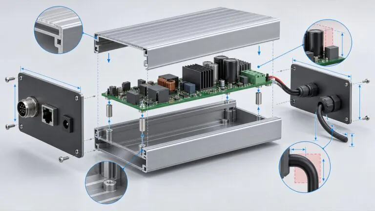
A controller PCB can fit inside an enclosure while its connectors, wiring access, or mounting arrangement make the product difficult to install. For hardware engineers developing industrial controllers, enclosure selection should begin with the complete mechanical envelope and the intended installation, before panel openings or finishes are released for manufacture.
Specify a custom aluminum controller enclosure by documenting the PCB assembly, external interfaces, mounting method, operating environment, and acceptance checks. Compare those requirements with existing profiles or enclosure structures, identify the necessary machining, and validate a representative sample. This approach gives the enclosure supplier a practical basis for assessing fit without transferring responsibility for the controller's electronics design or system verification.
Which Controller Details Define the Mechanical Envelope?
The mechanical envelope includes the board, installed components, connectors, fasteners, and the access needed to install or service them. A bare-board outline is a starting point, but it does not describe everything that must fit inside or around the enclosure.
| Design input | Information to provide | Question it resolves |
|---|---|---|
| PCB assembly | Outline, board thickness, component heights on both sides | Does the internal space accommodate the actual assembly? |
| Connector system | Installed connector models and mating cable details | Can the connector pass through the panel and be operated? |
| Internal hardware | Mounting holes, spacers, brackets, and fasteners | What supports the board and where is access required? |
| Installation space | Available space and neighboring equipment | Can the complete controller be installed and removed? |
- Use the populated assembly. Show components on both sides of the PCB, including items that extend beyond its outline. An enclosure choice based on the unpopulated board can overlook interference with the base or cover.
- Include removable parts. Identify plugs, terminal blocks, memory modules, or other items that need access. Describe whether the customer expects to remove them with the cover installed.
- Separate requirements from estimates. Label preliminary dimensions and identify who will confirm them. A provisional connector position should not silently become the manufacturing reference.
- Describe the intended orientation. Show how the product sits in use. Mounting orientation affects access to cables, covers, and fasteners even when the internal board arrangement is unchanged.
Statement: A bare PCB outline is enough to confirm enclosure fit.
Answer: False
Explanation: Component heights, connectors, mounting hardware, and installation access must also be evaluated.
When Can an Existing Aluminum Profile Be Reused?
An existing profile is a useful candidate when its cross-section, internal features, and panel arrangement suit the controller. It should be evaluated against the product requirements before assuming that machining can correct every mismatch.
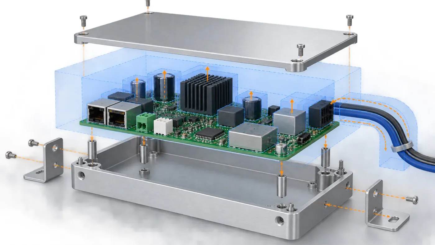
Illustrative clearance review; confirm dimensions against the selected profile.
- Check the cross-section first. Width, height, wall features, and existing board slots depend on the chosen profile. Changing the cut length does not freely change those features.
- Evaluate the panel arrangement. Confirm whether the enclosure allows the required connector layout and the customer's installation sequence. A suitable internal width alone does not establish a suitable product structure.
- Identify machining dependencies. Ask which openings, holes, or local features are feasible on the selected enclosure. Review access and remaining material rather than treating every requested cutout as automatically available.
- Keep another route available. If the existing options do not meet the requirements, evaluate a different structure, dedicated extrusion tooling, or another appropriate manufacturing route.
PUMAYCASE prioritizes reviewing existing profiles and enclosure options before assessing a dedicated solution. Reuse may reduce development work when the geometry fits; it does not guarantee lower cost, shorter delivery, or immediate stock availability.
Statement: Changing an extrusion's cut length also changes its internal width.
Answer: False
Explanation: Cut length and cross-sectional geometry are different design variables. A width mismatch may require another profile or manufacturing route.
How Should Connectors and Cable Access Be Specified?
Specify panel openings from the selected connector and its installed arrangement, using a consistent mechanical reference. Include how the customer will insert, secure, and remove the mating cable, rather than defining only the visible opening.
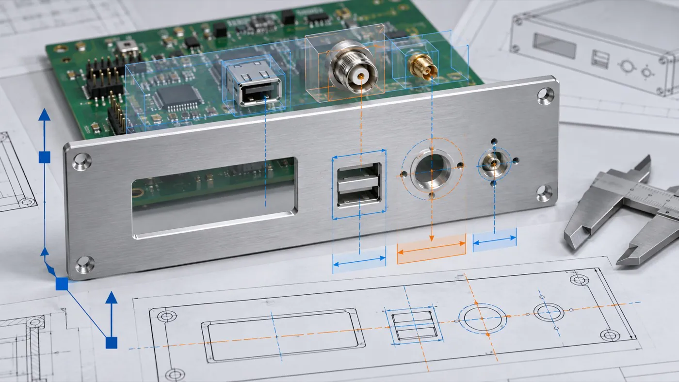
Illustrative connector and panel review, not a validated controller layout.
| Interface | Details to check | Useful evidence |
|---|---|---|
| Board-mounted connector | Position relative to the PCB and panel | Assembly drawing with common references |
| Panel-mounted connector | Fixing pattern and rear access | Manufacturer drawing and installation envelope |
| Removable terminal block | Plug removal and wire access | Representative plug and cable arrangement |
| Button or indicator | Operating access and panel position | Panel drawing and sample fit check |
- Control the reference system. Locate the board and panel features from defined datums. Independently dimensioned drawings can describe different assumptions about where the PCB sits.
- Confirm the installed connector. Include mounting hardware and any relevant sealing parts. A similar-looking connector is not a reliable substitute for the specified component.
- Review the cable in place. Use the intended cable and connector guidance to check clearance and access; do not invent a universal bend allowance.
Statement: Matching the connector opening guarantees that the connected cable can be installed.
Answer: False
Explanation: The mating plug, fastening access, and surrounding installation space still need review.
What Must Be Agreed About Mounting and Service Access?
The mounting method should support the intended installation while leaving the necessary access to connectors and enclosure fasteners. Describe the mounting arrangement as a requirement to evaluate, rather than assuming every enclosure accepts the same bracket or rail adapter.
| Mounting requirement | Information to confirm |
|---|---|
| Mounting surface | Available fixing locations and installation space |
| Service access | Parts to remove and access needed for their fasteners |
| Mechanical accessories | Supplier and customer responsibilities |
- Specify the mounting surface. Show the panel, cabinet, machine structure, or rail arrangement, together with the available fixing locations.
- Define removal expectations. State whether the customer needs to remove the cover, PCB, or complete enclosure during service. Review that sequence before approving inaccessible fixing points.
- Identify hardware responsibility. List which mechanical accessories belong in the enclosure supply and which the customer will provide. Do not leave brackets or fasteners implicit.
- Check a representative installation. Trial the sample in the intended space with surrounding equipment represented. A bench fit check cannot resolve every installation constraint.
Statement: Mounting compatibility should be checked for the selected enclosure and accessory combination.
Answer: True
Explanation: A general mounting description does not establish that a particular bracket, adapter, or fixing arrangement fits.
Which Environmental and Surface Requirements Affect the Design?
Describe actual use conditions and the functions the enclosure must support before selecting openings, finishes, or interface details. Aluminum material and a product category name do not establish the complete controller's thermal, ingress, or EMC performance.
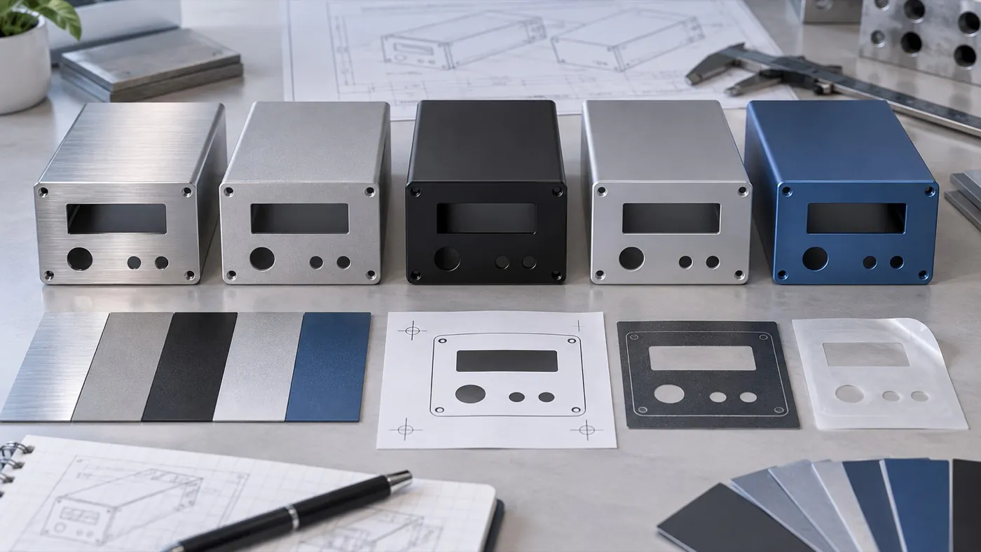
Review appearance alongside functional interface requirements.
- Describe exposure. Identify indoor or outdoor use and relevant dust, moisture, cleaning, or other exposure. A protection target must be evaluated for the complete configuration, including openings and connectors.
- Provide thermal inputs. Share the electronics team's heat-loss estimates, operating conditions, and proposed heat-transfer interfaces. Validate cooling using a representative product instead of relying on aluminum alone.
- Identify functional surfaces. Mark surfaces involved in electrical contact, mechanical fit, or thermal interfaces so that their requirements can be reviewed alongside the finish.
- Define appearance acceptance. Specify visible surfaces, color references, markings, and any agreed sample approval method. Finish and marking combinations require project-specific confirmation.
Statement: An aluminum enclosure alone guarantees that the finished controller passes EMC testing.
Answer: False
Explanation: Complete-product performance depends on the electronics, interfaces, structure, installation, and applicable validation.
What Should the Customer Verify With the First Sample?
The sample should test the assumptions that could change the enclosure design or prevent the controller from being installed. Agree on the checks before ordering the sample so that acceptance refers to defined requirements.
| Review area | Sample check | Record to retain |
|---|---|---|
| Internal fit | Install the representative PCB and mechanical hardware | Interference findings and approved changes |
| External access | Fit the intended connectors and cables | Access observations and panel revisions |
| Mounting | Trial the specified mounting arrangement | Confirmed installation configuration |
| Appearance | Compare finish and markings with agreed requirements | Approved references and exceptions |
| Product performance | Conduct the customer's required system validation | Results linked to the tested configuration |
- Use representative parts. Substituting different connectors or hardware can leave the critical interface untested.
- Close exceptions explicitly. If the sample is accepted with changes, identify those changes and decide what additional evidence is needed before production.
- Separate responsibilities. PUMAYCASE supplies customized enclosures and agreed mechanical deliverables; it does not provide PCB installation, wiring, or finished electronics assembly. Complete-controller testing and certification are not assumed enclosure services.
What Information Should Be Released for Repeat Orders?
Release a controlled set of mechanical files and approved requirements so that repeat orders refer to the same configuration. A previous sample or purchase-order description alone can leave important details ambiguous.
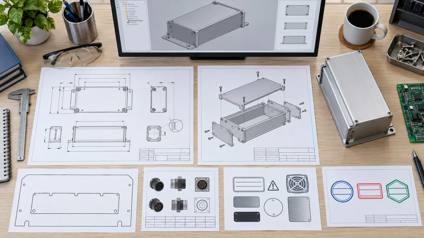
Illustrative document package; retain the actual approved revisions for repeat orders.
- Record revisions together. Identify the enclosure drawing, panel artwork, finish reference, and accessory list used for the approved configuration.
- Document quantities and packaging. Confirm order quantities, protection needs, and delivery information for each project rather than assuming fixed commercial terms.
- Review later changes. A new PCB, connector, or installation arrangement may require enclosure changes even if the product name remains the same.
A controlled release gives engineering and purchasing a shared reference for subsequent requests and helps the supplier identify what has changed.
Conclusion
Specify a custom aluminum controller enclosure around the populated PCB, actual connectors, installation access, operating requirements, and sample acceptance criteria. Evaluate existing profiles where they fit, confirm necessary machining and finishes, and retain the approved configuration for repeat supply. Send PUMAYCASE your PCB envelope, available drawings, connector positions, mounting requirements, finish requirements, and target quantities to assess a suitable enclosure route.