
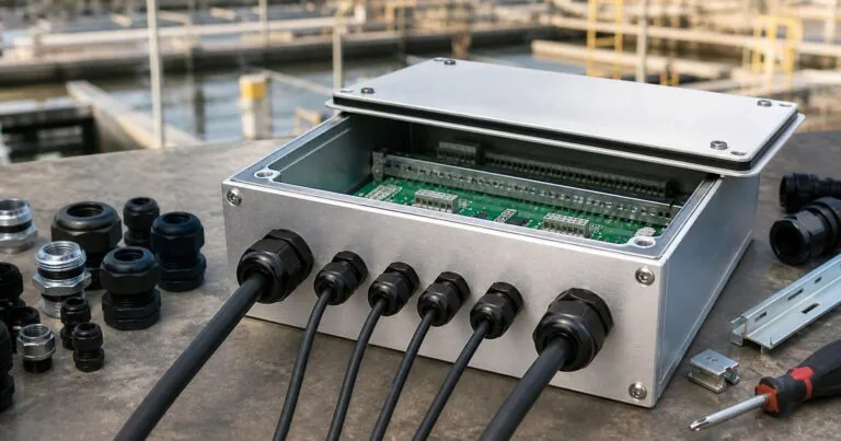
Waterproof Aluminum Enclosure Cable Gland Layout: How Should Engineers Plan It?
Cable entries often fail first. One small spacing error can ruin sealing, assembly, and lead time. A clear waterproof aluminum enclosure cable gland layout prevents rework.
A good waterproof aluminum enclosure cable gland layout defines cable direction, gland size, wall thickness, gasket clearance, CNC tolerance, and service access before machining. This helps engineers keep IP67 or IP68 sealing realistic while reducing prototype changes.
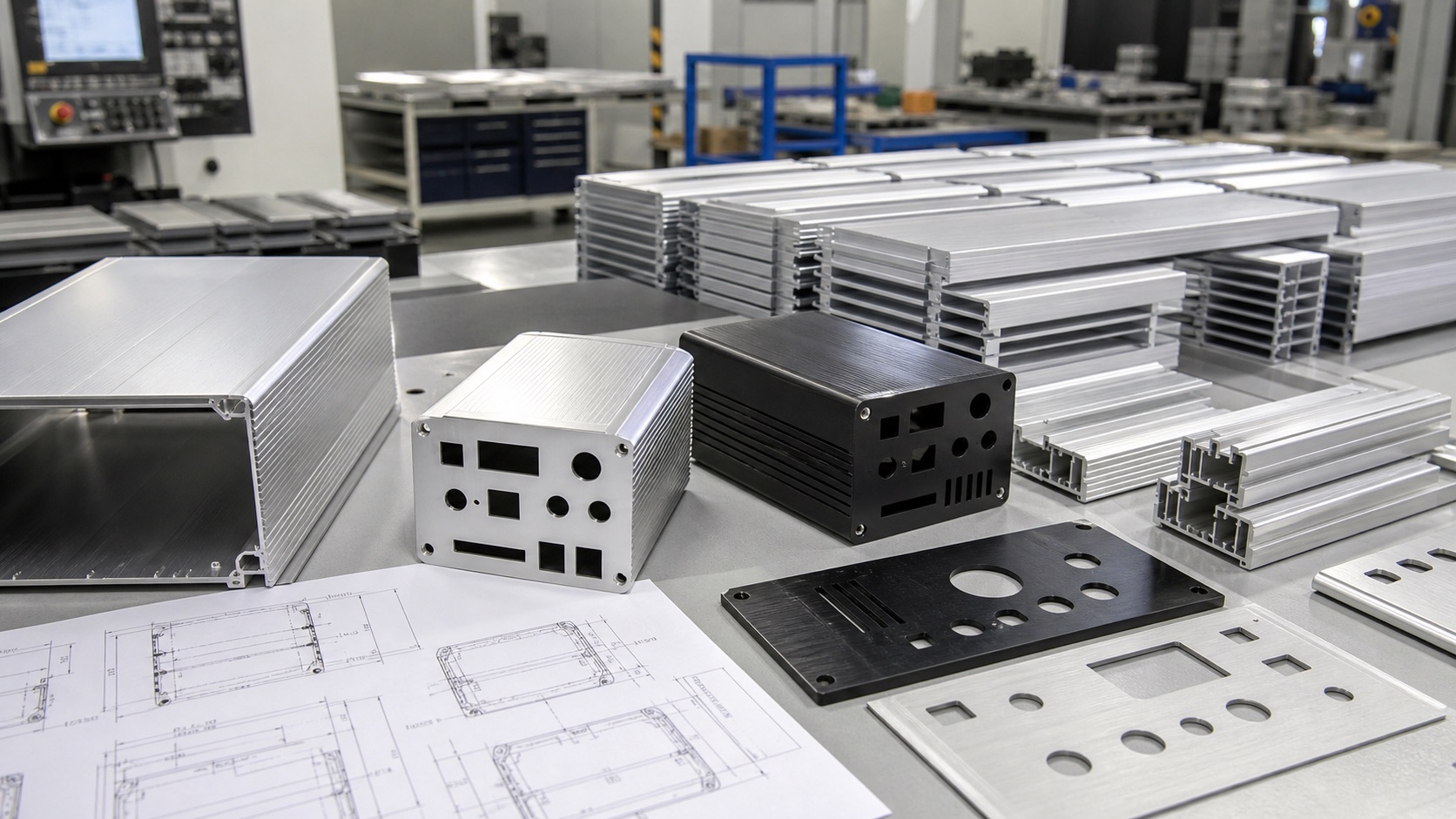
I see this problem often when engineers design compact outdoor devices. The PCB is ready. The connector list is fixed. The enclosure size looks correct. But when the sample arrives, the cable gland touches the PCB, the locknut has no room, or the cable bends too sharply. In this guide, I will explain how I plan cable gland layout for sealed aluminum enclosures before CNC machining starts.
Where Should Cable Glands Be Placed on a Waterproof Aluminum Enclosure?
Many designs place glands where space looks empty. That space disappears after cables, locknuts, tools, and gaskets are added. A layout check prevents this.
Cable glands should be placed where the cable can enter straight, the locknut can tighten fully, the gasket line stays clear, and the internal PCB or terminal block has enough service room.
Start With the Cable Path, Not the Hole
When I review a waterproof enclosure drawing, I do not start with the hole center. I start with the cable path. Jeff may tell me that the project uses two M12 sensor connectors, one antenna connector, and one M20 cable gland for power input. These parts look small on a 2D drawing, but they need space in three directions.
The outside of the enclosure needs enough room for the cable bend radius. The inside needs room for the locknut, sealing washer, terminal connection, and hand tool. The panel surface needs enough flat area for compression. If one of these is missing, the enclosure may look good but assemble badly.
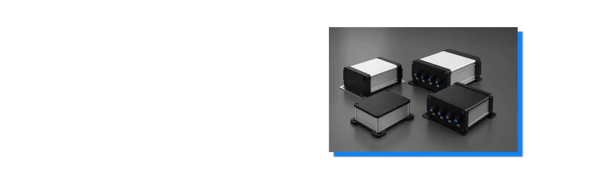
For outdoor IoT and smart sensor boxes, I often suggest placing cable glands on one end plate instead of spreading them across many walls. This can simplify CNC machining and improve service access. It also keeps the waterproof risk in one controlled area. For custom projects, PUMAYCASE can review the connector list and help plan waterproof aluminum enclosures before the first sample.
| Layout Point | Common Mistake | Better Choice |
|---|---|---|
| Cable direction | Cable exits upward and collects water | Let cable exit downward or sideways when possible |
| Gland spacing | Wrench cannot tighten locknut | Keep tool clearance around each gland |
| Gasket area | Hole is too close to cover seal | Keep CNC cutouts outside the gasket compression path |
| PCB clearance | Connector body hits components | Check 3D model with connector length and wiring |
| Mounting direction | Cable blocks wall screws | Check field installation before machining |
I also ask about installation. A factory wall-mounted controller is different from a solar monitoring box on a pole. A device under a machine may need cable entry from the bottom. A weather station may need side entry to avoid water sitting around the gland. The IEC 60529 IP Code defines enclosure protection levels, but the layout still has to match the real mounting direction.
How Does CNC Machining Affect Cable Gland Sealing?
A waterproof design can fail during machining. Burrs, thin walls, rough edges, and poor flatness damage sealing. CNC planning protects the gland interface.
CNC machining affects cable gland sealing through hole tolerance, edge finish, wall thickness, surface flatness, and machining sequence. A clean circular hole with deburred edges helps the washer compress evenly.
The Washer Needs a Flat and Clean Seat
Many cable glands use a sealing washer on the outside face of the enclosure. That washer needs a flat surface. If the gland hole is near a rib, curve, slot, screw boss, or raised logo area, the washer may not sit evenly. Water does not need a large path. It only needs a small gap.
This is why I prefer to confirm gland size before finalizing the enclosure wall. Metric cable glands such as M12, M16, M20, and M25 need different hole diameters and different washer contact areas. If Jeff sends only "four cable holes" without the gland model, the first sample may need rework. If he sends the gland datasheet, cable diameter, nut size, and washer outer diameter, our CNC drawing can be much more reliable.
Anodizing and powder coating also matter. A thick coating can slightly change fit at threaded holes or tight connector cutouts. Sharp machined edges can damage washers during assembly. For this reason, I normally check deburring, chamfer size, and finish sequence with the customer. PUMAYCASE supports CNC aluminum enclosure machining for end plates, front panels, rear panels, and custom aluminum housings.
| CNC Detail | Why It Matters | Practical Check |
|---|---|---|
| Hole diameter | Controls gland fit and washer centering | Match gland datasheet, not only thread name |
| Deburring | Prevents washer cuts and cable damage | Add light chamfer or burr removal note |
| Wall thickness | Affects thread engagement and locknut fit | Check gland clamping range |
| Flat area | Allows even gasket compression | Avoid ribs, curves, and step faces |
| Finish thickness | Can affect tight cutouts | Define finish before final tolerance review |
I also remind buyers that IP claims depend on the full assembly. A high-rated cable gland cannot save a poor panel surface. A good aluminum body cannot save a loose gland. In North America, engineers may also compare enclosure needs with NEMA enclosure environmental standards. These standards help frame protection goals, but the drawing must still control the actual machining details.
How Can Engineers Prepare a Cable Gland Layout for IP67 or IP68 Testing?
IP testing can expose small design mistakes. If the sample fails, the schedule becomes painful. A checklist before machining reduces that risk.
Engineers should prepare for IP67 or IP68 testing by confirming gland ratings, cable diameter range, gasket compression, screw torque, mounting direction, and full assembly method before sample production.
Test the Real Assembly, Not an Ideal Box
I always tell customers that a waterproof enclosure should be tested as a complete product. The body, cover gasket, screws, cable glands, connectors, vents, labels, and cables all affect the result. If Jeff tests an empty box with plugged holes, the result may not match the final device with real cables.
For IP67, many engineers think only about short immersion. For IP68, the test condition needs clear agreement because depth and time are not always the same for every product. The IEC standard page for degrees of protection provided by enclosures is a useful reference, but buyers should still define the exact test goal with the lab or customer.
The current outdoor electronics trend makes this more important. Edge sensors and industrial IoT gateways are smaller than older control boxes. They also carry more connectors, antennas, and power cables. This means less room for sealing surfaces and less tolerance for late changes. A careful layout can save several days or weeks because the first CNC sample is closer to production.
| IP Preparation Item | What to Confirm | Why It Reduces Risk |
|---|---|---|
| Gland IP rating | Rating with actual cable diameter | Prevents loose sealing around cable jacket |
| Cable jacket | Roundness, hardness, and diameter tolerance | Gland seals on the cable, not only the hole |
| Cover gasket | Material, groove depth, and screw spacing | Keeps compression stable after assembly |
| Screw torque | Assembly method and torque range | Avoids uneven gasket pressure |
| Test sample | Final cables, connectors, labels, and vents | Matches real product conditions |
For PUMAYCASE projects, I like to ask for the 2D drawing, STEP file, PCB size, connector datasheets, cable diameter, target IP rating, finish color, sample quantity, and expected annual volume. This information helps us review the custom aluminum enclosure solutions as one system. It also helps us give practical feedback within 24 hours instead of only quoting a metal box.
I also pay attention to lead time. If the cable gland layout is clear, CNC programming is faster. If the finish requirement is clear, anodizing or powder coating can be planned earlier. If the sample inspection checklist is clear, the buyer can approve the enclosure faster. This is why layout preparation is not only an engineering detail. It is also a schedule control tool.
Conclusion
A waterproof aluminum enclosure cable gland layout protects sealing, assembly, and lead time when engineers plan cable direction, CNC details, and IP testing together.