Machine Vision Aluminum Enclosure: How Can Engineers Protect Cameras in Harsh Factories?
Machine vision cameras fail when heat, dust, vibration, and washdown are ignored. That delay hurts inspection accuracy. A machine vision aluminum enclosure solves these risks early.
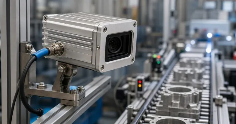
A machine vision aluminum enclosure protects industrial cameras by combining sealed lens windows, CNC machined connector panels, heat paths, anodized surfaces, and stable mounting features for factories, outdoor inspection, robotics, and AI vision devices.
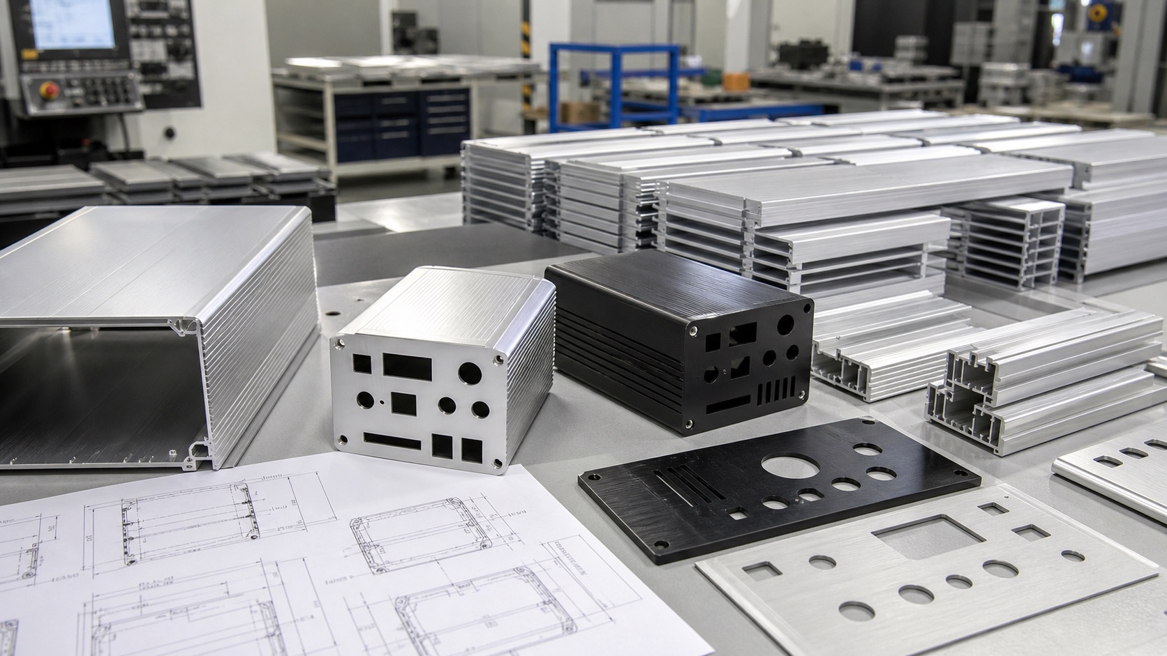
I see more engineers adding cameras near conveyors, robots, packaging lines, and outdoor inspection stations. The camera is small, but the enclosure decision is not small. If Jeff wants stable images and fewer field failures, he must plan sealing, heat, mounting, cable exit, and service access together.
Why Does A Machine Vision Aluminum Enclosure Need More Than A Simple Box?
A camera box looks easy at first. But one bad lens seal or loose mount can ruin inspection data. A planned enclosure protects optical and electrical performance.
A machine vision aluminum enclosure needs lens sealing, rigid alignment, heat transfer, IP-rated cable exits, and clean grounding because camera accuracy depends on both protection and stable mechanical position.
The Lens Area Is The First Risk
I often remind engineers that a vision enclosure has two jobs. It must protect the camera, and it must protect the image. A normal electronics enclosure can hide inside a cabinet. A machine vision unit must look outside. That means the lens window, front ring, gasket, and mounting face become part of the optical system.
If the lens tube is too short, the lens may touch the window. If it is too long, the unit becomes heavy and harder to mount near moving equipment. If the front gasket has uneven compression, water can enter around the window. If the window material is not selected well, glare and scratches can reduce inspection accuracy.
This is why I prefer to review the camera model, lens size, working distance, cable direction, and mounting method before confirming the enclosure shape. For PUMAYCASE custom aluminum enclosure solutions, we can machine end plates, front windows, brackets, and connector holes around the real device stack, not only around an outside dimension.
| Design Area | Common Mistake | Better Engineering Choice |
|---|---|---|
| Lens window | Window selected after enclosure design | Confirm optical diameter and cleaning condition first |
| Front gasket | Flat gasket with uneven compression | Use a controlled groove and stable screw pattern |
| Camera position | PCB or camera floats inside | Use machined standoffs or a fixed mounting plate |
| Cable exit | Connector added late | Reserve IP-rated connector space from the first drawing |
The current smart manufacturing trend makes this more important. A 2026 NIST roadmap on AI and machine learning for smart manufacturing highlights advanced sensing and perception as key parts of future factories. If the camera enclosure is weak, the AI model receives weak data.
How Should Engineers Balance IP Protection And Heat Dissipation?
Sealed camera housings trap heat. Heat can raise sensor noise and shorten component life. Aluminum helps when the heat path is designed before CNC machining.
Engineers should balance IP protection and heat dissipation by using an aluminum body as a heat spreader, keeping gasket areas sealed, and giving hot components direct contact to the enclosure wall.
A Sealed Design Still Needs A Heat Path
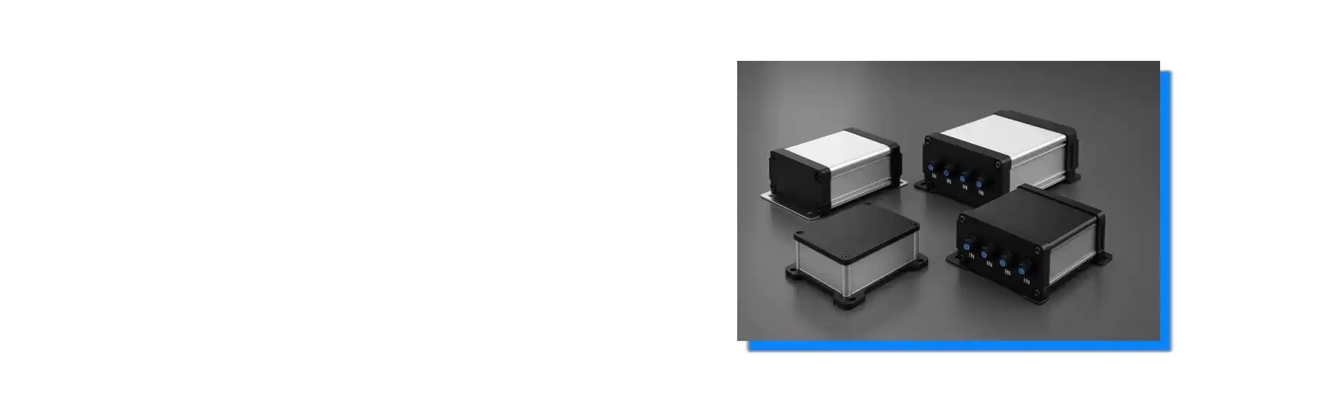
Many engineers ask me for an IP67 camera housing and a compact size at the same time. I understand why. Factory space is tight. Robot arms and inspection fixtures do not leave much room. But a sealed enclosure has less natural airflow, so the heat must move through conduction.
Aluminum is useful because it conducts heat much better than many plastics. Technical references such as Engineering ToolBox aluminum thermophysical properties show why aluminum is often chosen when heat transfer matters. But material alone does not fix the problem. The heat source must touch the aluminum through a planned path.
For a compact vision device, I usually ask where the sensor board, processor, LED driver, or power module sits. If the hot part is floating in air, the enclosure cannot help much. If we add a machined boss, thermal pad area, inner plate, or thicker wall section, the aluminum body can spread heat to the outside.
| Heat Question | Why It Matters | Practical Enclosure Detail |
|---|---|---|
| Where is the main heat source? | It decides the shortest heat path | Add a boss or flat contact pad |
| Is the housing sealed? | Less airflow means more conduction work | Avoid relying on internal air movement |
| Is the unit near a hot machine? | Ambient heat reduces thermal margin | Use more surface area or fins |
| Will it be cleaned with water? | Vents may break IP protection | Keep sealing strategy clear |
For IP planning, I also refer engineers to the official IEC 60529 standard page, because IP ratings are not marketing words. They describe test conditions. A connector, window, vent, or screw can lower the whole assembly rating if it is not sealed correctly.
PUMAYCASE can support waterproof aluminum enclosures with CNC machined panels, gasket grooves, and anodized surfaces. But I still need the customer to share real heat load, installation direction, and connector information. Good sealing and good cooling must be designed together.
What CNC Customization Details Reduce Prototype Delays?
Prototype delays often come from small mismatches. A connector hole is 0.5 mm off, or a cable bend is forgotten. CNC review reduces these surprises.
CNC customization reduces machine vision enclosure delays by confirming connector drawings, lens clearance, screw torque space, PCB mounting height, tolerance stack, surface finish, and cable routing before production starts.
Small Drawing Gaps Become Real Assembly Problems
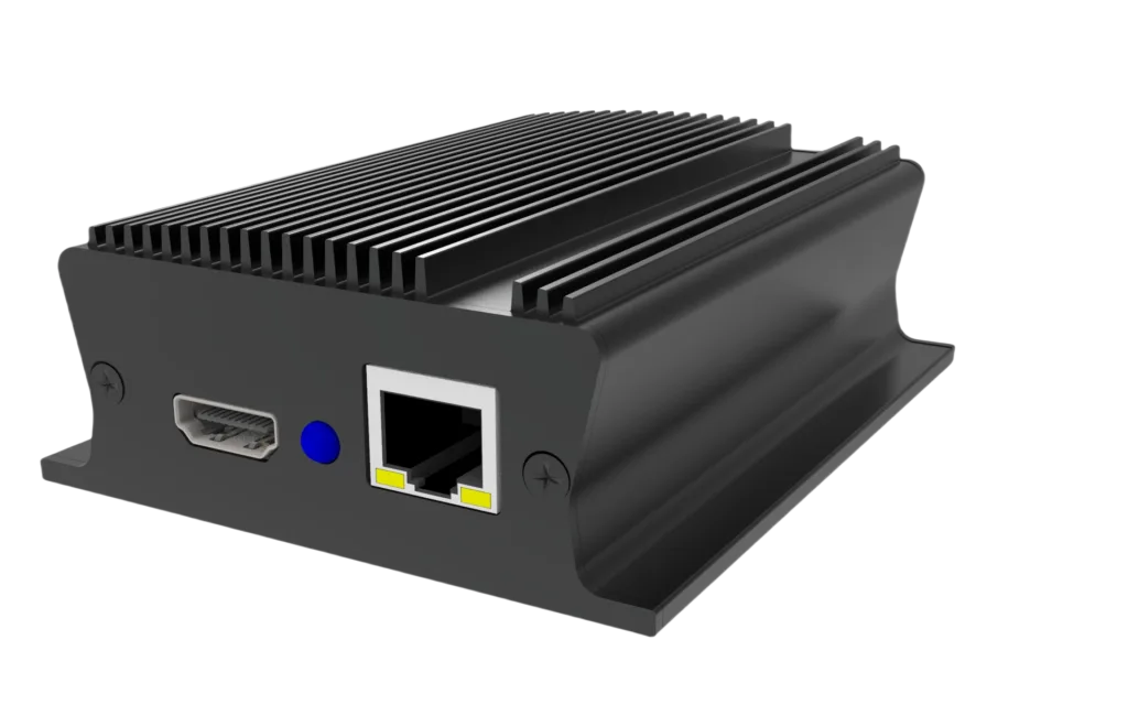
I have seen many prototype problems that did not come from the aluminum profile itself. They came from missing details. A connector datasheet showed the thread, but not the panel cutout. A lens diameter was listed, but the focus ring needed extra finger clearance. A mounting screw looked fine in 3D, but the screwdriver could not reach it after assembly.
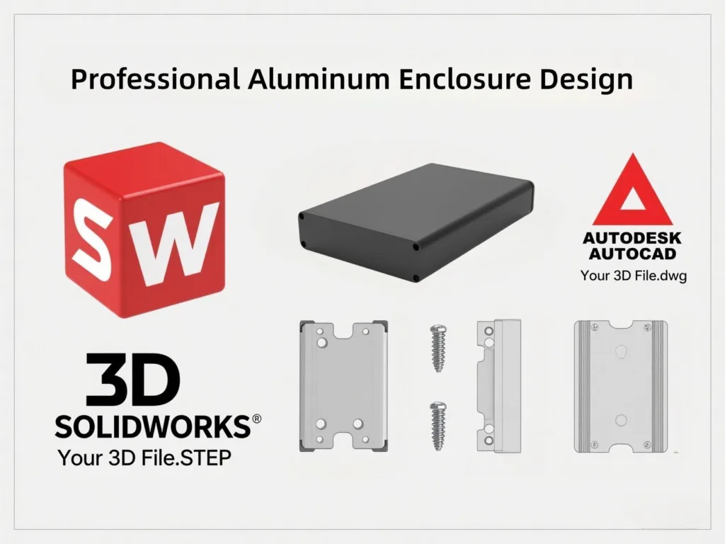
This is why I like early drawing feedback. When a customer sends a STEP file, 2D drawing, connector datasheet, and sample photo, we can check the weak points faster. For CNC aluminum enclosure machining, the most useful information is not only the outer size. It is the assembly logic.
| CNC Detail | What To Confirm | Why It Prevents Delay |
|---|---|---|
| Connector cutout | Thread, nut clearance, gasket face | Prevents loose or leaking connectors |
| Lens opening | Lens OD, window size, focus access | Prevents blocked image or service issue |
| Mounting holes | Screw size, bracket load, datum face | Keeps camera alignment stable |
| Surface treatment | Anodizing color, masked contact area | Supports appearance and grounding needs |
| Marking | Logo, direction arrow, serial number | Reduces field installation mistakes |
The enclosure supplier should also discuss tolerance stack. If the camera bracket, PCB, lens tube, and end plate come from different suppliers, each tolerance can look acceptable alone. Together, they can move the lens center or stress a connector.
I usually suggest one controlled datum face for the camera mount and one clear reference for connector locations. This makes inspection easier. It also helps when the design moves from prototype to small-batch production.
External engineering resources such as NI’s guide on what to consider when selecting an enclosure also point to temperature, cable entry, clear space, and environmental protection. These are simple ideas, but they are easy to miss when the schedule is tight.
Conclusion
A machine vision aluminum enclosure protects image quality, electronics, and lead time when sealing, heat, CNC details, and mounting are planned together from the first design review.