
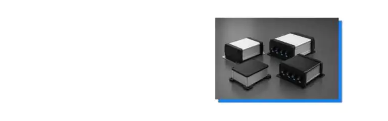
Choosing between IP65 and IP68 affects more than the enclosure label. For an industrial controller, outdoor sensor, communications gateway, or monitoring device, the decision can change the sealing structure, connector selection, maintenance plan, verification method, and quotation scope.
IP65 and IP68 both address dust and water ingress, but they describe different water-exposure conditions under the IEC 60529 classification system.[1] Engineers should define the actual environment first, then evaluate the enclosure, openings, seals, mounting direction, and finished assembly as one system.
What Do IP65 and IP68 Actually State?
IP65 and IP68 share the same first digit, but their second digits cover different water tests. The rating should therefore be treated as a defined verification target, not as a general claim that one enclosure is “more waterproof” in every installation.
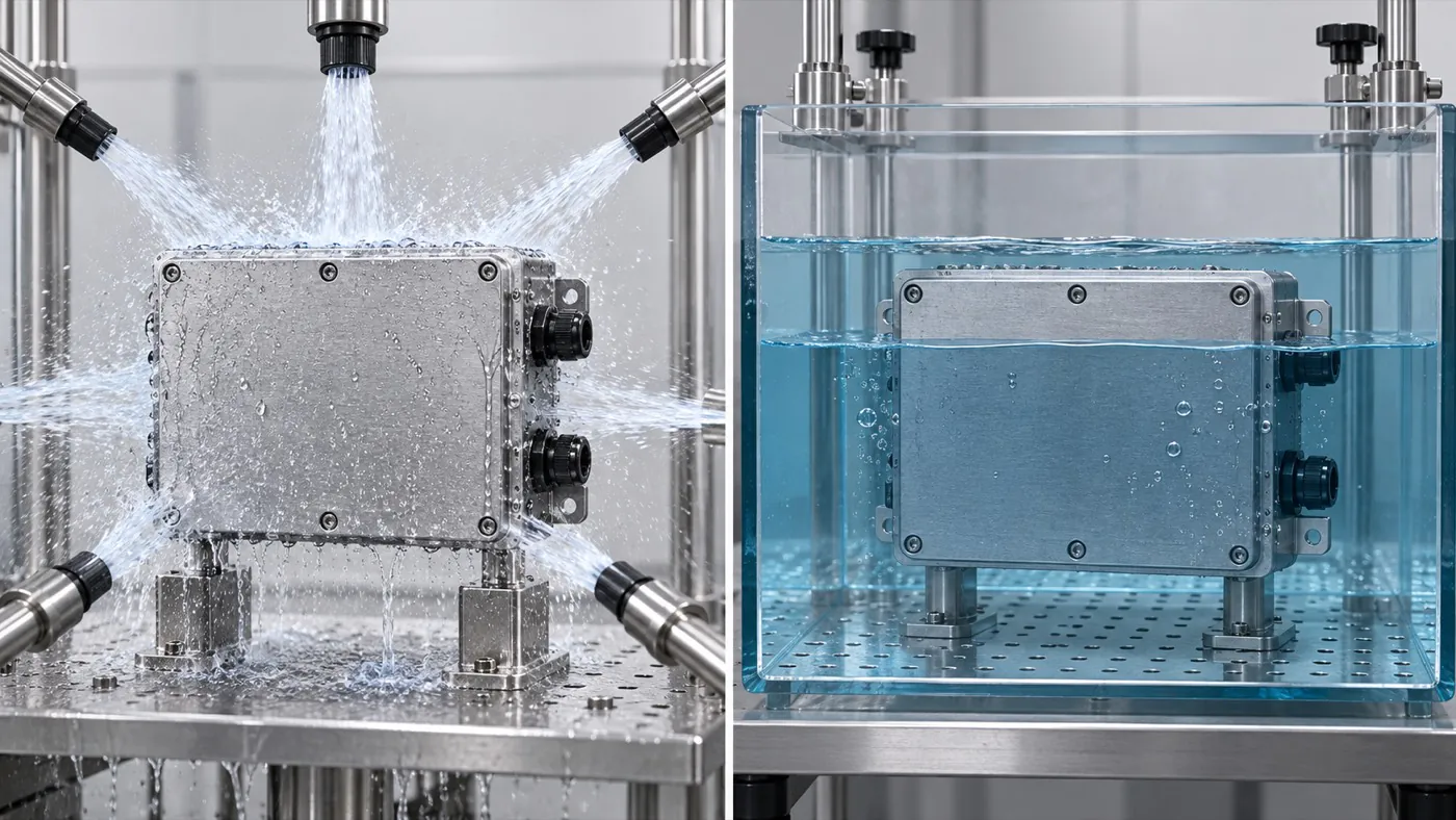
IP65 and IP68 describe different exposure conditions, so the target must follow the actual application.
| Rating element | What it indicates | Project implication |
|---|---|---|
| First digit: 6 | Dust-tight classification | Dust protection is not the main difference between IP65 and IP68 |
| Second digit: 5 | Protection against water jets | The project must define where jets or spray may reach the finished enclosure |
| Second digit: 8 | Protection for continuous immersion under specified conditions | Depth, duration, configuration, and acceptance criteria must be agreed |
- Read both digits together. The first digit concerns access and solid-particle ingress; the second concerns water ingress. A water-related decision should not ignore how the product is assembled and serviced.
- Define IP68 conditions in writing. IP68 is not an unlimited-depth or unlimited-time statement. The relevant immersion conditions need to be documented for the project.
- Separate a design target from a verified result. Selecting an enclosure described as IP65 or IP68 does not by itself prove that a customized, populated device will meet the same rating.
- Identify the test configuration. Covers, fasteners, gaskets, cable glands, connectors, vents, and machined openings should match the configuration used for verification.
Statement: An IP68 label means an enclosure can remain at any depth for an unlimited time.
Answer: False
Explanation: IP68 immersion conditions must be specified; the label alone does not define unlimited depth or duration.
Which Exposure Conditions Should Define the Target?
The target rating should follow credible exposure scenarios at the installation site. Rain, cleaning jets, temporary flooding, and sustained immersion are different events, so engineers should not use a broad phrase such as “outdoor use” as the complete requirement.
| Exposure question | Information to provide | Why it changes the choice |
|---|---|---|
| Where is the device installed? | Indoor, sheltered outdoor, exposed outdoor, underground, mobile, or near water | Orientation and water paths differ |
| How does water reach it? | Rain, splash, directed jet, cleaning process, standing water, or immersion | The applicable water test and sealing details differ |
| How long can exposure last? | Intermittent, temporary, or sustained | Duration may affect the target and validation plan |
| What else is present? | Dust, salt, chemicals, oils, UV, and temperature cycling | Finish, seal material, and maintenance may need separate review |
- Describe the worst credible event. Include direction, duration, frequency, and whether water can collect around a lid or connector.
- Account for mounting orientation. A downward-facing cable entry may behave differently from an upward-facing opening where water can pool.
- Include cleaning procedures. If equipment is washed, state the cleaning method rather than assuming an outdoor rating automatically covers it.
- Review temperature and pressure changes. Thermal cycling can create pressure differences and condensation risks that an ingress label alone does not resolve.
An application may also need corrosion, UV, impact, electrical safety, or EMC evaluation. Those requirements are separate from the two digits in an IP rating and should be specified independently.
Statement: “Outdoor use” provides enough information to select between IP65 and IP68.
Answer: False
Explanation: Outdoor exposure can range from sheltered rain to flooding, and the water path, duration, orientation, and maintenance conditions still need definition.
How Do Cutouts, Connectors, and Cable Entries Affect Protection?
Every opening becomes part of the ingress-control system. A suitable enclosure body cannot compensate for an incompatible connector, an incorrectly sized gland hole, damaged sealing surfaces, or a display opening without a validated seal.
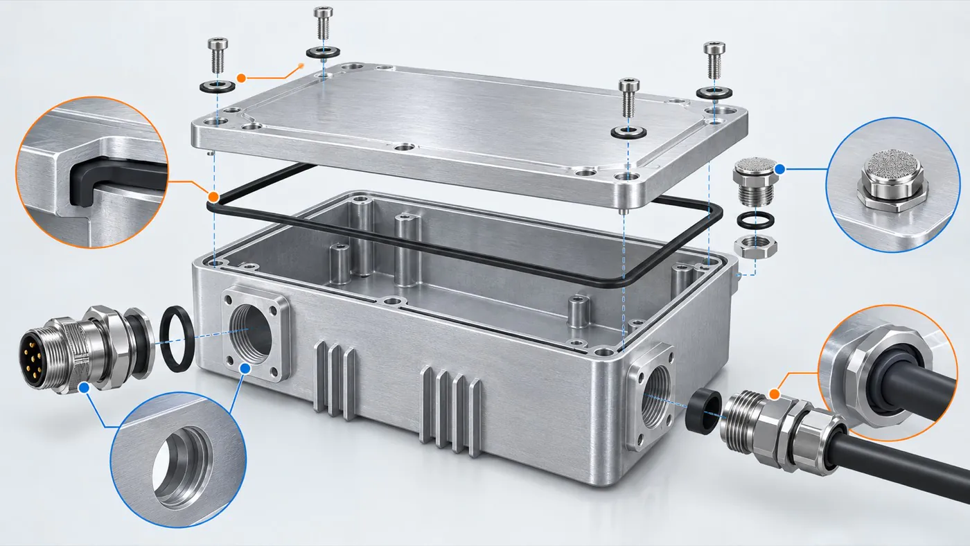
Every joint, opening, connector, and cable entry belongs in the enclosure protection review.
| Interface feature | Required input | Check before release |
|---|---|---|
| Cable gland | Manufacturer, part number, thread, cable range, and installation torque if specified | Hole size, wall thickness, thread engagement, orientation, and sealing washer |
| Panel connector | Datasheet, panel cutout, seal arrangement, and mating condition | Cutout tolerance, fastener pattern, gasket contact, and external exposure |
| Display or window | Viewing area, bonding or gasket method, and material | Flatness, compression, adhesive compatibility, and edge sealing |
| Pressure vent | Vent model, airflow need, location, and contamination exposure | Installation direction, clearance, and effect on the verification plan |
- Freeze component part numbers early. Similar-looking glands and connectors may require different cutouts or sealing methods.
- Dimension from controlled datums. Hole locations should relate to the PCB, panel, and mounting features through a consistent drawing scheme.
- Protect sealing lands. Machining, scratches, burrs, coating buildup, or engraving near a gasket path can change contact conditions.
- Plan installation instructions. Seal placement, fastener sequence, and specified component torque may matter when the customer assembles the product.
PUMAYCASE can machine openings and prepare an enclosure for the customer’s connectors and PCB arrangement. The customer remains responsible for installing the electronics and validating the complete device; PUMAYCASE does not provide PCB installation, wiring, or box-build assembly.
Statement: A machined opening can be added without reviewing its effect on the enclosure’s ingress protection.
Answer: False
Explanation: The cutout, interface component, seal, mounting direction, and assembly method can all affect the finished product’s protection.
Which Enclosure Structure and Customization Route Fits the Project?
The best route depends on internal space, external exposure, interface layout, mounting, quantities, and the required validation path. Existing extrusion or enclosure designs are worth evaluating first when their basic geometry and sealing concept fit, but they are not automatically suitable for every IP65 or IP68 project.
| Route | Suitable starting condition | Main limitation to check |
|---|---|---|
| Existing enclosure with custom machining | Internal section, closure, and sealing concept already fit the product | Cutouts and interfaces may change the tested configuration |
| Existing aluminum profile with custom length and panels | PCB width and internal height fit an available profile | End-panel sealing and allowable dimensional changes depend on the design |
| Die-cast enclosure with machined features | A suitable body size and lid structure already exist | Machining location, draft geometry, and sealing surfaces constrain changes |
| Dedicated or alternative custom solution | Existing designs cannot meet space, mounting, or sealing needs | Tooling, development work, and validation scope require project review |
- Start with the PCB and tallest components. Include keep-out zones, connector overhang, cable bend space, and access for customer assembly.
- Check the closure concept. Lid stiffness, gasket path, fastener locations, and compression consistency influence sealing feasibility.
- Keep claims configuration-specific. A base enclosure’s published rating may not transfer to a different length, panel, hole pattern, or accessory set.
- Escalate when the platform does not fit. If an existing option compromises sealing, mounting, or internal clearance, assess tooling or another manufacturing route instead of forcing the design.
Reusing an existing enclosure platform can reduce development steps when it already meets the project’s basic constraints. It cannot be promised to be faster, cheaper, or tooling-free until the actual design and quantity are reviewed.
Statement: Using an existing enclosure design guarantees that no tooling or additional validation will be required.
Answer: False
Explanation: Custom dimensions, interfaces, seals, and project-specific acceptance requirements may still require tooling changes, samples, or testing.
What Should Engineers Check in a Prototype?
A prototype should confirm mechanical fit, seal interfaces, customer assembly access, appearance, and the planned verification configuration. Visual approval alone is insufficient for an ingress-sensitive product.
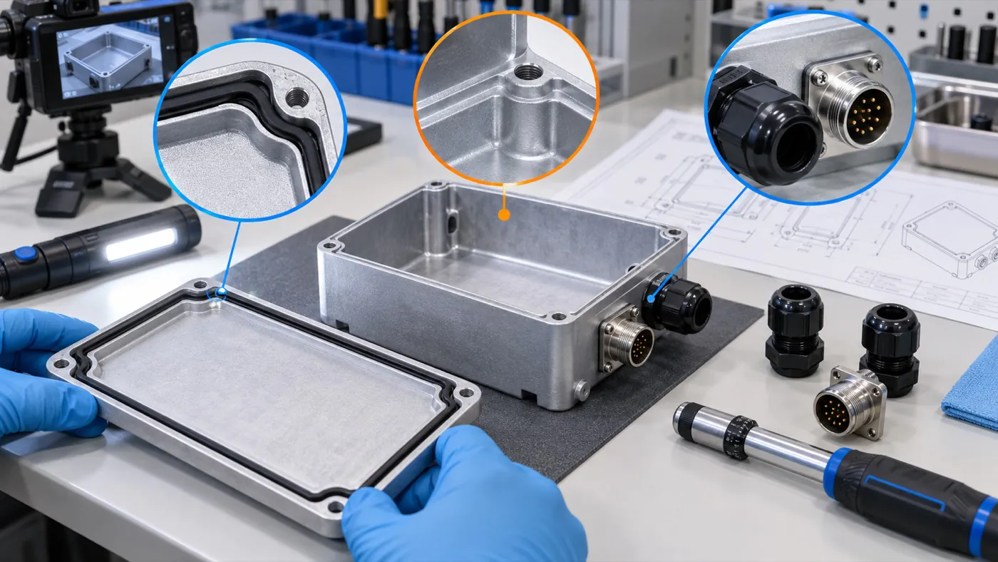
Prototype inspection should cover sealing surfaces, hardware, interfaces, and the intended assembled configuration.
| Prototype check | Evidence to review | Decision before production |
|---|---|---|
| PCB and component clearance | Installed-board check or controlled 3D data | Confirm no interference through tolerance and assembly conditions |
| Gasket and closure | Gasket continuity, seating, joint condition, and fastener access | Approve the exact seal and closure arrangement |
| Interfaces | Actual glands, connectors, windows, switches, and mating parts | Confirm fit, orientation, and installation method |
| Surface and marking | Approved color/texture range, logo artwork, and protected contact areas | Define cosmetic and functional acceptance criteria |
| Ingress verification | Agreed test configuration and result record | Decide whether redesign or production release is appropriate |
- Use representative components. Printed drawings alone may miss connector shoulders, washers, cable bend limits, or tool-access problems.
- Inspect the full gasket path. Look for joints, corners, machining marks, trapped debris, and uneven seating before testing.
- Verify repeatable assembly. The design should allow the customer to install the PCB and interfaces without disturbing seals or damaging finishes.
- Record the approved configuration. Photograph or document gasket, fasteners, connectors, vents, and orientation so later production is compared with the same baseline.
Any ingress test should use the agreed finished configuration. Passing a check on an unmachined body does not establish the result for a customized enclosure with installed interfaces.
Statement: A prototype that looks correct has fully validated the enclosure’s ingress performance.
Answer: False
Explanation: Appearance does not verify the behavior of seals, interfaces, fasteners, or the complete assembly under the agreed exposure conditions.
What Must Procurement Confirm Before Production?
Procurement should make the quotation and purchase specification configuration-specific. Comparable supplier quotations require the same drawings, component list, finish, inspection scope, packaging needs, and acceptance criteria.
| Control item | What to freeze | Why it matters for repeat orders |
|---|---|---|
| Drawing and revision | Enclosure, panels, hole patterns, gasket, and marking files | Prevents mixing obsolete and approved requirements |
| Interface components | Manufacturer and exact part number | Avoids silent changes to cutouts or sealing hardware |
| Verification scope | Sample quantity, configuration, method, responsibility, and records | Aligns expectations before production |
| Appearance | Finish, color reference, artwork, and inspection conditions | Makes cosmetic decisions reproducible |
| Supply details | Target quantity, packaging, labeling, and forecast assumptions | Supports an accurate project-specific quotation |
- Name the controlled revision on the order. File names alone may be ambiguous when several teams exchange drawings.
- Define who supplies interface parts. Glands, connectors, vents, seals, and fasteners must match the approved configuration.
- Agree on change control. A substitute seal or connector should trigger review before it reaches production.
- Retain sample approval evidence. The approved sample, comments, and inspection criteria provide the baseline for trial production and replenishment.
MOQ, sample quantity, price, lead time, and testing responsibility should be confirmed for the specific project. They should not be inferred from an IP rating or from another enclosure program.
How Can a Supplier Evaluate the Project Efficiently?
A supplier can evaluate the project faster when the inquiry connects environmental requirements to controlled mechanical information. The most useful package includes the PCB envelope, 2D or 3D drawings, interface part numbers, mounting method, exposure description, target rating, finish, marking, validation expectations, and expected quantities.
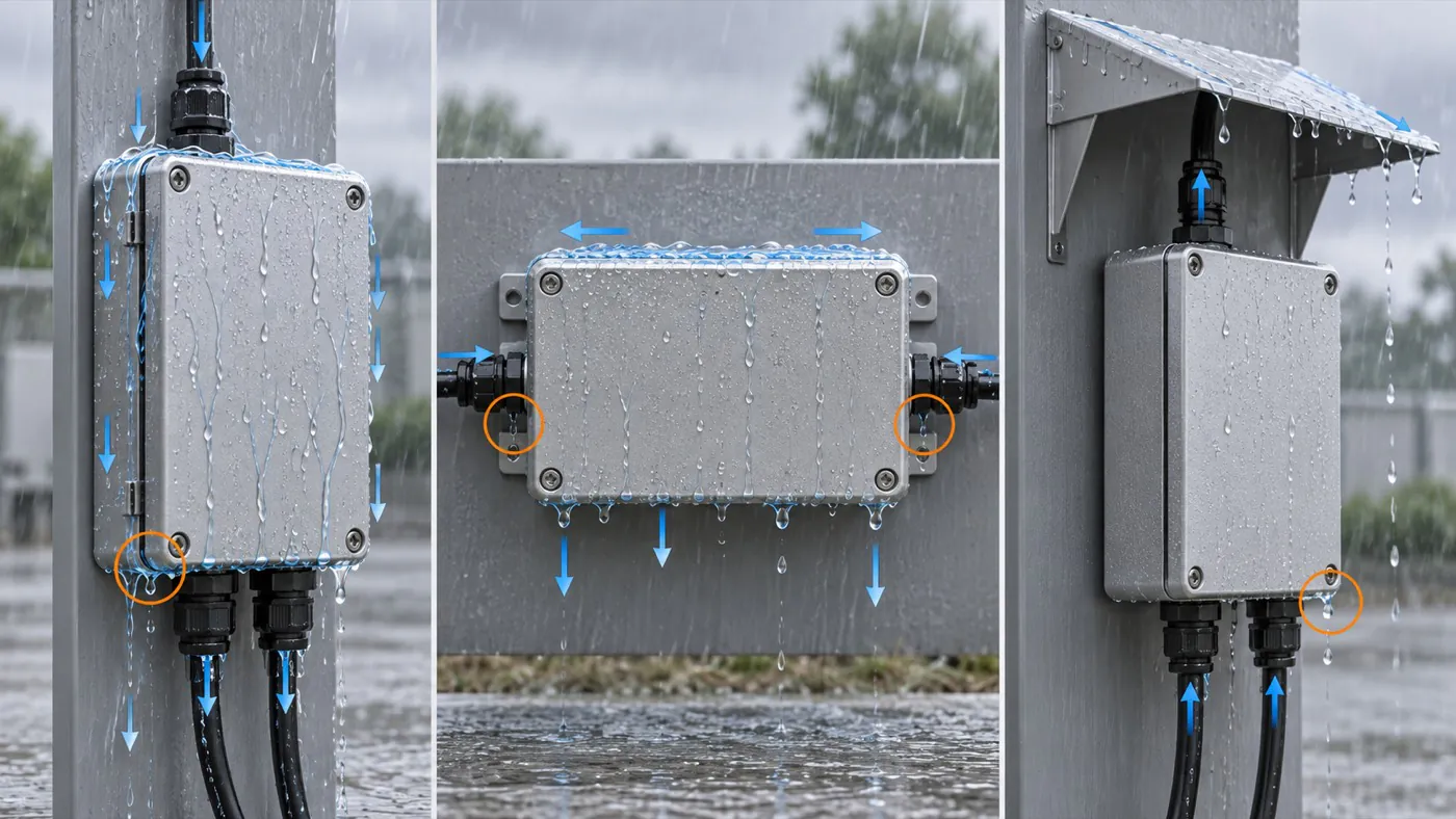
Mounting orientation and exposure paths help define the enclosure and validation requirements.
- Provide the PCB envelope and internal keep-outs. Include maximum component heights, connector projections, and customer assembly access.
- Identify every external interface. Attach manufacturer drawings for glands, connectors, switches, displays, and vents.
- Describe the installation. State orientation, mounting hardware, water direction, maintenance frequency, and the worst credible exposure.
- Separate required and preferred items. Mark the protection target, finish, color, logo, quantity, and validation documents as mandatory or optional.
PUMAYCASE can first assess whether an existing aluminum enclosure or profile provides a suitable basis, then review CNC machining, surface treatment, and marking. If the existing route does not fit the sealing, size, or mounting requirements, the next manufacturing option needs a project-specific assessment.
Conclusion
Engineers should choose between IP65 and IP68 by defining the real water exposure and verification conditions, then checking the entire configured enclosure: closure, gasket, cutouts, connectors, cable entries, mounting direction, finish, and customer assembly process. IP68 is appropriate only when its specified immersion conditions match the application; a higher number does not remove the need for prototype and finished-device validation. To evaluate a suitable enclosure and customization route, provide the PCB dimensions, interface part numbers, mounting method, environment, target quantity, finish, and required test scope.
References
- International Electrotechnical Commission, “IEC 60529: Degrees of protection provided by enclosures (IP Code),” https://webstore.iec.ch/en/publication/2452