
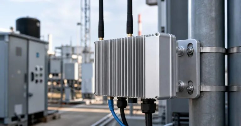
Industrial Wireless Gateway Aluminum Enclosure: How Can Engineers Balance RF, Heat, and IP Protection?
Industrial gateways fail when the enclosure blocks RF, traps heat, or leaks at connectors. This delays field tests. I solve it by planning these risks together.
An industrial wireless gateway aluminum enclosure should balance antenna performance, heat transfer, IP sealing, EMC grounding, and service access. Engineers should confirm antenna zones, cable entries, thermal pads, CNC cutouts, anodizing, and prototype drawings before machining starts.
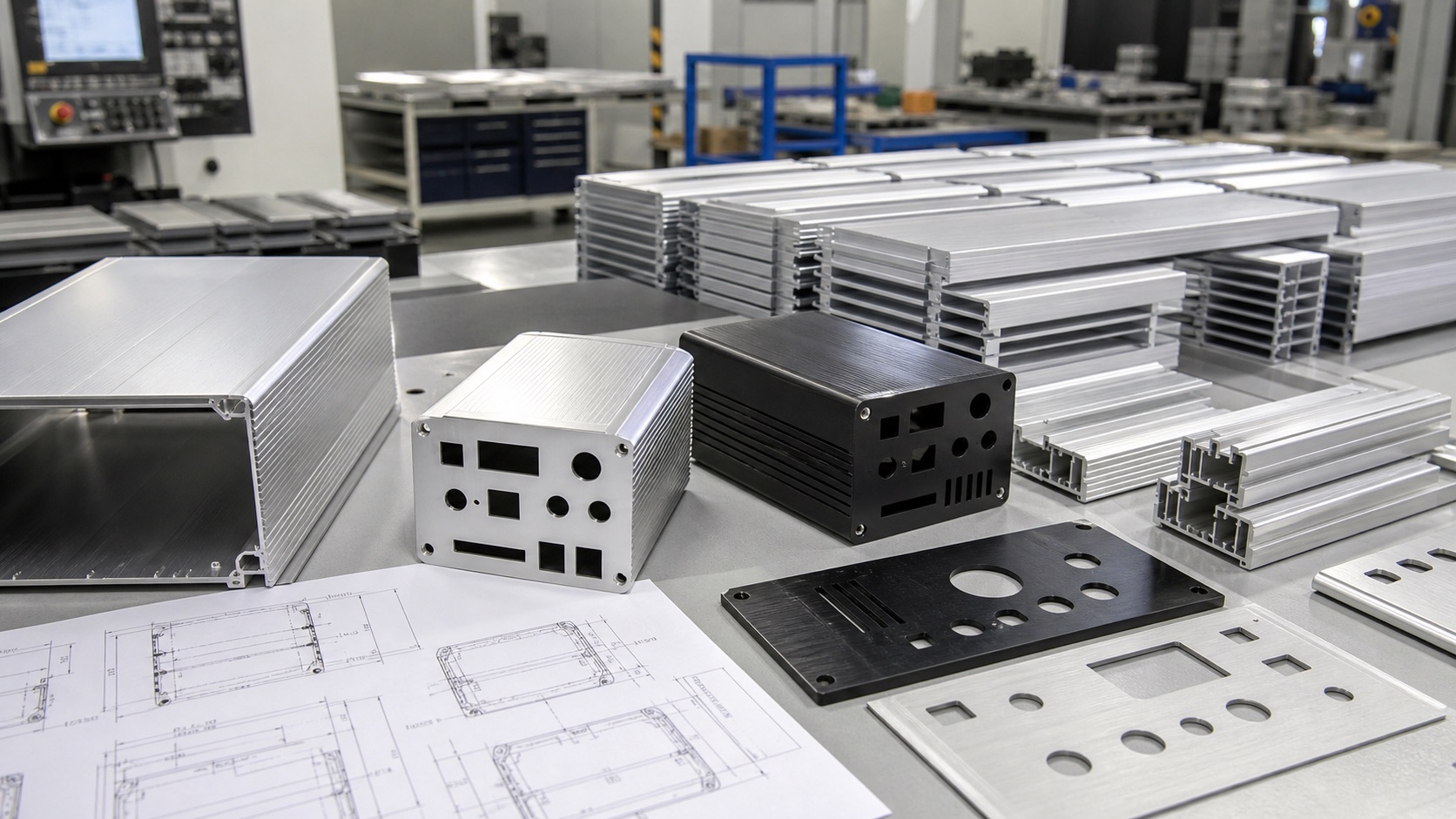
I see more industrial gateways used in smart factories, energy sites, machine rooms, and outdoor monitoring systems. These products look small, but they carry many design conflicts. The enclosure must protect electronics, but it must also let the device communicate, release heat, and stay easy to assemble.
Why Should Industrial Wireless Gateway Aluminum Enclosure RF Layout Be Planned Early?
Metal housings can weaken wireless signals when antenna space is added too late. This creates unstable communication. I avoid it by checking RF layout first.
RF layout should be planned early because aluminum blocks or reflects radio signals. Engineers should decide external antenna positions, RF connector spacing, grounding points, and cable paths before final CNC machining.
Antennas Need Mechanical Space, Not Only Electrical Approval
Many gateway projects arrive with a finished PCB and a simple request for two or four antenna holes. At first, this looks easy. We only need to machine SMA connector holes on the end plate. But the real RF problem is often hidden behind the hole position.
The NIST Industrial Wireless Systems project explains that industrial wireless work must handle reliability, latency, resilience, interference, and real factory conditions. This matches what I see in enclosure projects. A metal enclosure gives good strength and basic shielding, but it can also block wireless signals if the antenna plan is weak.
For an industrial gateway, I usually ask Jeff to confirm the number of antennas, antenna type, connector thread, cable bending space, mounting direction, and nearby metal obstacles. If the gateway will sit inside a cabinet, on a wall, or near a machine frame, the antenna direction matters. If the antenna is close to a large aluminum surface, the signal may change.
| RF Detail | Common Risk | Practical Check |
|---|---|---|
| SMA connector spacing | Antennas hit each other during assembly | Check antenna diameter and rotation clearance |
| Internal RF cable | Cable bends too sharply | Keep a smooth cable route from PCB to panel |
| Metal cover near antenna | Signal loss or unstable range | Use external antenna or planned RF window |
| Grounding contact | Noise path is unclear | Define conductive contact before anodizing |
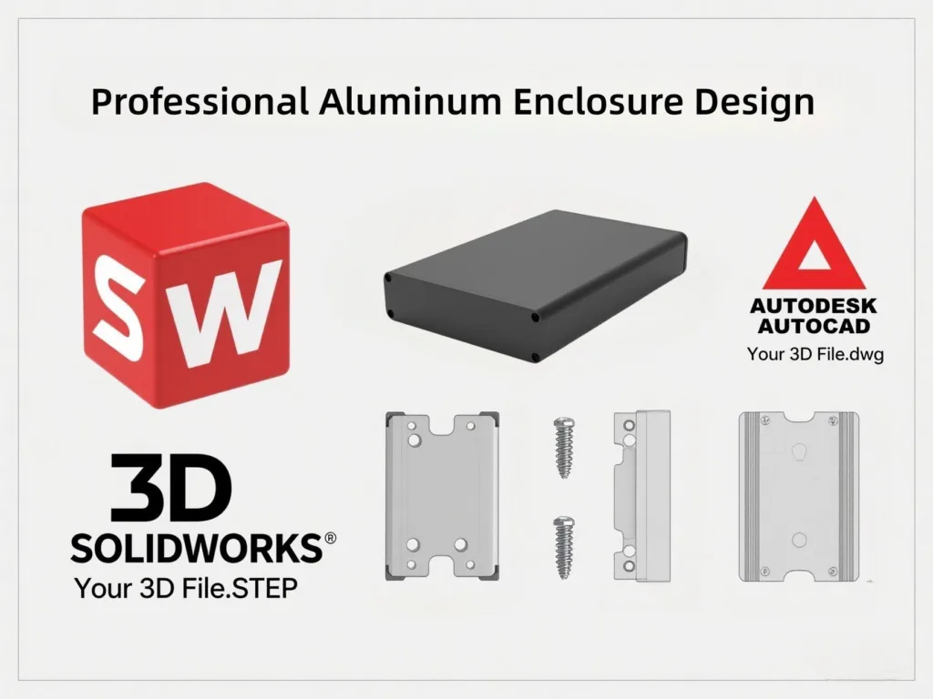
For custom aluminum enclosure solutions, I prefer to review the gateway as a full assembly. A STEP file with antennas, PCB, connectors, and brackets is much better than a flat panel drawing alone. If the design needs Wi-Fi, 4G, LoRa, Bluetooth, or private industrial wireless, the mechanical design should leave room for RF parts before we discuss surface finish and logo marking.
How Can Engineers Control Heat in a Sealed Industrial Gateway?
Sealed gateways often run hot because processors and modems stay active for long periods. Heat shortens component life. I use aluminum as the heat path.
Engineers can control heat by moving heat from chips to the aluminum enclosure. They can use thermal pads, internal ribs, thicker contact areas, external fins, and careful PCB placement.
A Sealed Box Needs a Conduction Plan
Industrial gateways now do more than simple data transfer. Many products handle protocol conversion, local data processing, security, and sometimes edge computing. This trend makes the enclosure smaller and hotter at the same time.
The first mistake is to think that aluminum alone will solve heat. Aluminum helps because it spreads heat well, but the heat must reach the aluminum first. If the hot chip only warms the air inside a sealed box, the enclosure surface may stay cooler while the PCB becomes too hot. In this case, the material is good, but the heat path is broken.
The NI enclosure selection guide reminds engineers to consider temperature range, clearance, and cable management when selecting an enclosure. I agree with this. In a gateway project, I want to know the main heat sources, power level, ambient temperature, installation direction, and whether the enclosure will face sun or cabinet heat.
| Heat Design Choice | When It Helps | Enclosure Impact |
|---|---|---|
| Thermal pad to wall | Hot processor or power module | Needs flat internal contact area |
| Extruded fin profile | Continuous medium heat | Uses body surface as passive heat sink |
| Light anodized color | Outdoor sun exposure | May reduce surface temperature rise |
| Larger internal air gap | Short peak heat only | Helps less than a real conduction path |
For extruded aluminum enclosures, fins and wall thickness can support passive cooling without adding a fan. For waterproof gateway designs, I avoid open vents unless the customer has a rated vent membrane plan. If Jeff needs IP67 protection, I would rather discuss thermal pads, contact bosses, and mounting orientation before cutting ventilation slots that may damage the sealing target.
Surface treatment also matters. Anodizing improves corrosion resistance and appearance, but it can affect electrical contact. If the same surface must support EMC grounding, we may need a masked area, conductive gasket, or screw contact point.
What Should Engineers Check Before CNC Machining IP-Rated Gateway End Plates?
Connector holes look simple, but small errors can break sealing or assembly. Rework wastes lead time. I prevent this with a CNC review checklist.
Before CNC machining, engineers should check connector datasheets, gasket land, cable gland thread depth, screw positions, tolerance notes, finish requirements, and assembly direction. This improves IP-rated gateway enclosure reliability.
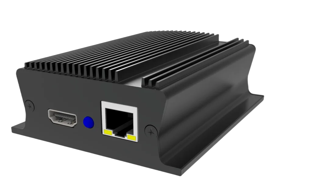
IP Protection Depends on the Final Assembly
When a customer asks for IP67 or IP68, I do not only check the enclosure size. I check the final assembled device. The end plate, gasket, screws, cable glands, antenna connectors, SIM slot cover, USB cover, and pressure path all matter.
The IEC IP ratings page explains how IP codes describe protection against solid objects and water. The NEMA enclosures page also describes enclosures as protection for electrical and electronic equipment in industrial and utility applications. These references are useful, but the engineer still has to translate the rating into real parts.
For example, a gateway may need two M12 connectors, two SMA antenna ports, one Ethernet gland, one power gland, and LED light pipes. Each hole removes material from the end plate. If holes are too close to the gasket groove, the sealing land becomes weak. If the nut clearance is not checked, the connector may fit in CAD but fail during assembly.
| CNC Check Item | Why It Matters | File to Provide |
|---|---|---|
| Connector datasheet | Confirms cutout, thread, and nut space | PDF or supplier drawing |
| STEP assembly | Shows PCB and cable position | 3D model |
| Gasket groove or seal land | Controls compression | 2D drawing with dimensions |
| Surface finish note | Avoids wrong anodizing or marking | Drawing and color sample |
| Quantity plan | Helps choose prototype or batch method | RFQ note |
For CNC aluminum enclosure machining, clear drawings save more time than urgent messages after production starts. I also suggest keeping a revision table. If Jeff changes an Ethernet port from RJ45 to M12, or changes an antenna from straight to right-angle type, the drawing should show the new version clearly.
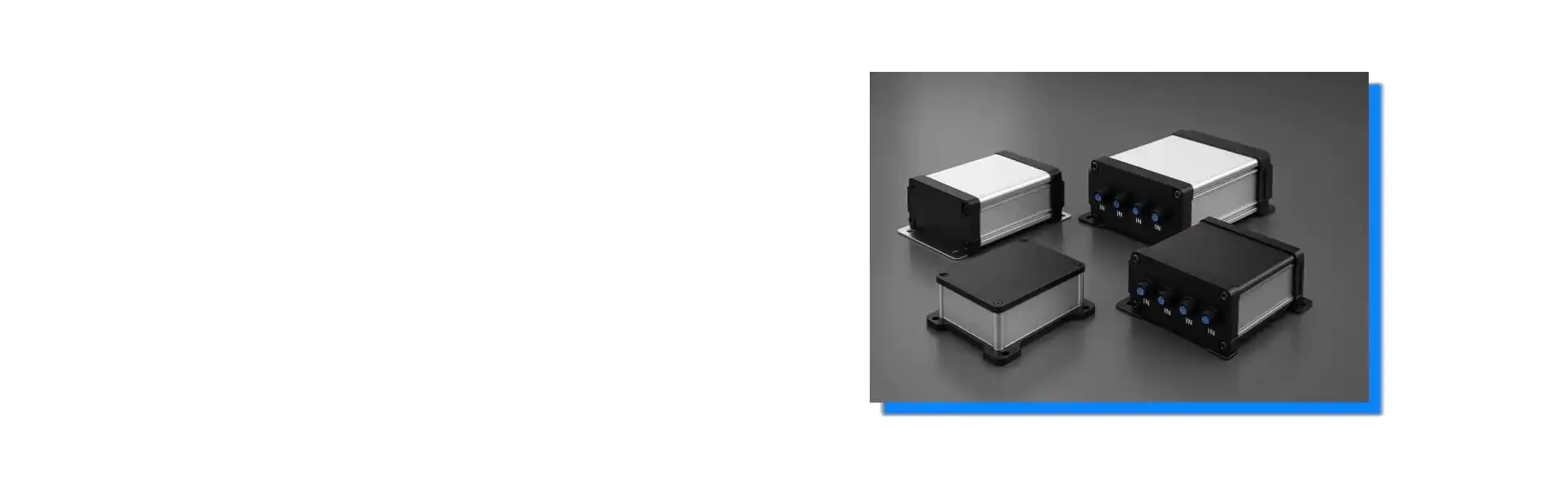
At PUMAYCASE, I like modular aluminum extrusions with CNC machined end plates for many gateway projects. This method supports small-batch customization, fast connector changes, anodizing, laser marking, silk screen printing, and later repeat production. It also helps engineers protect lead time because we can change the end plate without changing the whole enclosure body.
Conclusion
An industrial wireless gateway aluminum enclosure works best when RF layout, heat flow, IP sealing, CNC machining, and lead time are planned as one design.