A loose PCB can rattle, short, or fail vibration tests. A poor thermal mount[^1] guarantees overheating. Use the enclosure's internal geometry as your most reliable mounting tool for maximum stability and performance.
The most reliable method is sliding the PCB into integral card slots[^2] within the extrusion profile. For fixed mounting, use CNC-machined standoffs with screws. For thermal transfer, ensure the PCB has a path for direct contact with the aluminum chassis, enhanced with a thermal interface material.
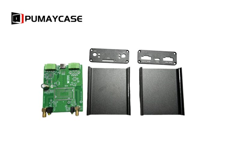
 "PCB mounting slots in aluminum extrusion"
The mounting method you choose is a fundamental design decision that impacts manufacturability, reliability, and thermal performance. Let’s break down the best approach for your specific application.
What is the Most Reliable, Cost-Effective Mounting Method?
You’re tired of dealing with extra brackets, tiny screws, and complex assembly instructions. Aligning a PCB on separate standoffs is slow, adds to the BOM, and is a common point of failure.
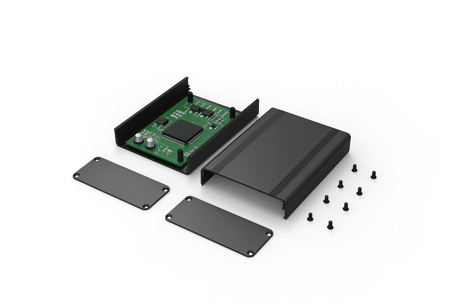
Using integral card slots, designed directly into the extrusion profile, is the most reliable and cost-effective method for most applications. It eliminates extra hardware, simplifies assembly to a single sliding motion, and ensures perfect alignment every time.
 "Integrated card slots for simple PCB assembly")
This method leverages the best part of the extrusion process. When we design the extrusion die, we can add slots or grooves with incredibly tight tolerances (typically ±0.1mm). Your PCB simply slides into these channels, held securely in place by the enclosure's own structure.
The "Add-On Rail" Mistake
A common mistake I see engineers make is selecting a standard, off-the-shelf box and then trying to fit a custom PCB inside it using aftermarket plastic or metal mounting rails. This approach is fraught with problems: the rails can break, the screws can vibrate loose, and the tolerance stack-up between the box, the rail, and the PCB can lead to misalignment with front and rear panel connectors.
The professional solution is to design the mounting feature into the enclosure from the start.
Case Example: Simplifying an IoT Gateway
A client came to us with a design for an industrial IoT gateway. Their initial prototype used an off-the-shelf enclosure and a separate, 3D-printed plastic cradle to hold the PCB. Assembly was a multi-step process, and the plastic was a potential failure point in high-temperature environments[^3]. We redesigned the enclosure as a custom extrusion with two precise card slots.
The result?
- Assembly time was cut by over 60%.
- The Bill of Materials[^4] was reduced by three parts (cradle and screws).
- The final product was far more robust and passed vibration testing on the first try.
Integrated Card Slots vs. Add-On Brackets
| Feature | Integrated Card Slots | Add-On Rails / Brackets |
|---|---|---|
| Reliability | Excellent. Part of the core structure. | Fair. An additional point of mechanical failure. |
| Assembly Time | Minimal. Slide in, secure end plates. | High. Requires screwing in brackets, then the PCB. |
| Part Count | Lowest. No extra hardware needed. | High. Adds brackets, screws, and complexity. |
| Cost at Scale | Lower. Die cost is amortized over the production run. | Higher. Ongoing cost of hardware and labor. |
| Design Flexibility | Limited. PCB must be rectangular and slide in. | Higher. Can mount non-standard PCB shapes. |
For any high-volume or high-reliability product, designing the slots into the extrusion is the superior engineering choice.
When Should I Use Screws and Standoffs Instead of Slots?
Your board has tall capacitors near the edge, or your application involves severe shock and vibration. Card slots are great for alignment, but they don't provide rigid Z-axis support.
Use screw bosses or standoffs when your PCB cannot slide in or requires absolute positional rigidity against forces on all axes. Standoffs are CNC-machined features that provide precise, fixed mounting points for screwing the PCB directly to the enclosure chassis.
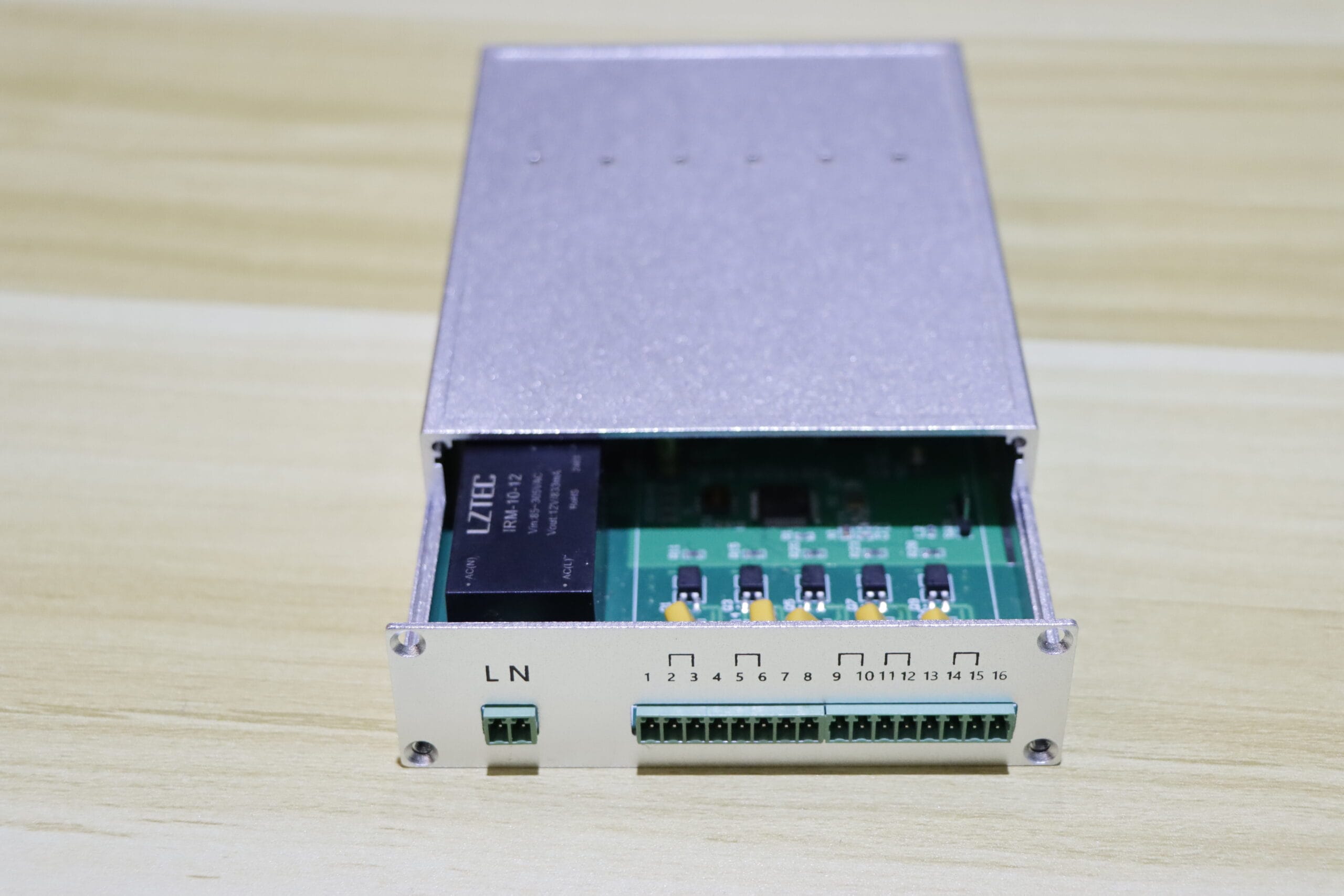
 "PCB mounting with standoffs and screws"
This method is about brute-force mechanical stability[^5]. We use a CNC machine to create raised cylindrical bosses (standoffs) on the interior surface of the enclosure. We then drill and tap these bosses to accept a screw (typically M2.5 or M3). Your PCB, with corresponding holes, sits on these standoffs and is clamped down firmly.
A Critical Design Trade-Off: Screw Access
There are two ways to execute this:
- Screws from the PCB Side: This is the most common method. The standoffs are in the enclosure base, and you screw down through the PCB. Pro: Easy to disassemble. Con: You need clearance around the screw head for a tool and the operator's hand.
- Screws from the Enclosure Exterior: The standoffs have a through-hole, and the screw is inserted from the outside of the enclosure into a threaded insert on the PCB. Pro: Tamper-resistant and creates a perfectly smooth internal surface. Con: Assembly is more complex, and you have exposed screw heads on the outside.
Field Experience: Surviving Extreme Vibration
We worked with an avionics company designing a controller for agricultural drones. Their initial prototype used card slots, but the intense vibration from the rotors caused intermittent failures at the card-edge connectors. The PCB was physically moving back and forth by a fraction of a millimeter.
We moved to a design with a solid, flat-bottomed extrusion. We machined six M3 standoffs into the base. The PCB was screwed down tightly onto the bosses. This completely eliminated the micro-vibrations and the unit passed its rigorous DO-160 vibration certification[^6]. It’s a perfect example of choosing the right mounting method for the operational environment.
How Do I Mount a PCB for Maximum Heat Dissipation?
Your board has a high-wattage FET[^7], a powerful processor, or an LED array that's creating a thermal hotspot. A simple fan isn't an option. You need to get that heat off the board and into the environment.
For maximum heat transfer, mount your PCB to create a direct, low-resistance thermal path from the component to the aluminum enclosure. This requires machining a perfectly flat surface on the enclosure interior and bridging the gap with a high-performance thermal interface material (TIM).
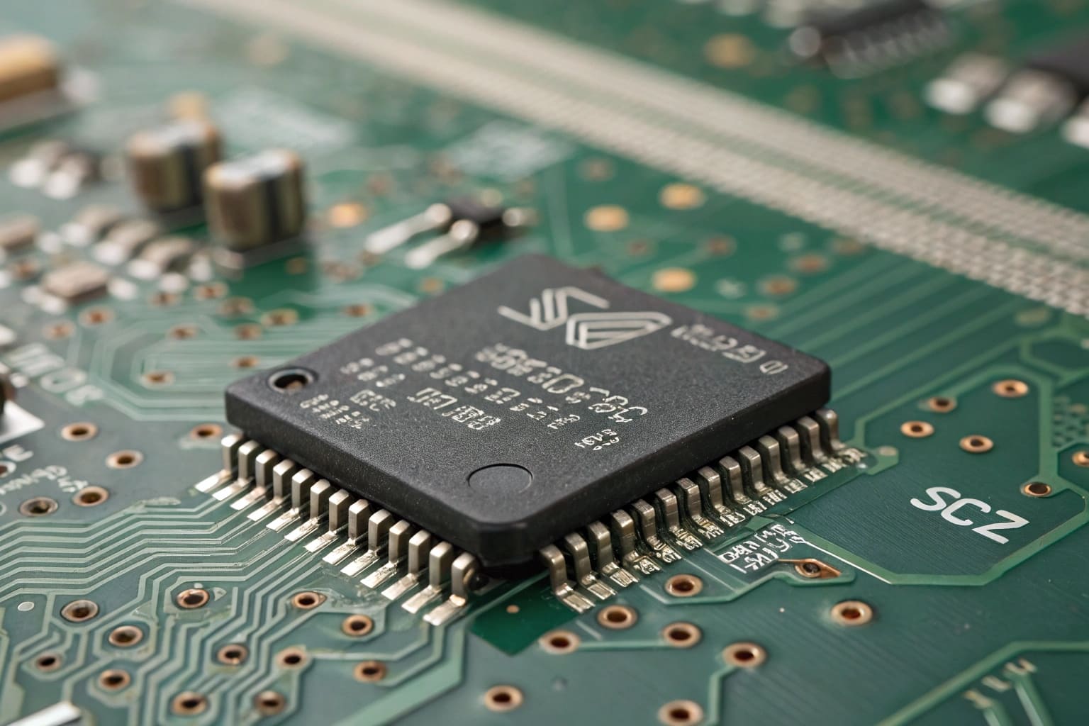
 "Thermal mounting for PCB heat dissipation"
In high-power electronics, you must stop thinking of the enclosure as just a box. The enclosure is your primary heatsink. The goal is to make the journey for heat from the component to the outside air as easy as possible.
Designing the Thermal Path
The efficiency of your cooling depends entirely on the quality of this path:
- Component (e.g., CPU): The source of the heat.
- PCB Substrate: Heat travels through thermal vias in the PCB to a solid copper plane on the bottom side.
- The Gap: This is the most critical point. Air is a terrible conductor. You must fill this gap.
- Thermal Interface Material (TIM): A thermal pad or grease that fills microscopic air gaps to ensure efficient conduction.
- Enclosure Body: A flat, machined surface on the enclosure receives the heat.
- External Fins: The heat spreads through the aluminum and is dissipated into the ambient air from the external heatsink fins.
The Importance of a Machined Surface
A raw extruded surface is not flat enough for good thermal contact. It has slight variations, lines, and imperfections. To create an effective thermal connection, you must specify a secondary CNC machining operation (like fly cutting) to create a perfectly flat "landing pad" for the PCB. This adds a small cost but can improve thermal performance by 5-10°C, which can be the difference between passing and failing.
We recently helped an industrial LED lighting client who was struggling with overheating. Their 60W driver board, simply screwed into a standard extrusion, was hitting 95°C. By machining a 100mm x 50mm flat landing pad into the enclosure base and adding a 0.5mm silicone thermal pad, we brought the operating temperature down to 78°C under the same load—a massive improvement in performance and long-term reliability.
Conclusion
Don’t treat mounting as an afterthought. It's a core design decision that impacts reliability, assembly cost, and thermal performance. Design the mount, design the enclosure, and design for success from day one.
---

[^1]: Learn how proper thermal mounting can prevent overheating and improve the lifespan of your PCB.
[^2]: Discover the advantages of using integral card slots for PCB mounting and how they simplify assembly.
[^3]: Find insights on designing PCBs that can withstand high temperatures without failure.
[^4]: Learn strategies to minimize BOM costs while maintaining quality in PCB manufacturing.
[^5]: Learn about the importance of mechanical stability in ensuring the longevity of PCBs.
[^6]: Understand the standards and importance of DO-160 certification for PCB reliability.
[^7]: Discover effective strategies for managing heat in high-wattage FET applications.