Taking a concept from your screen to a physical, ready-to-use enclosure is a long journey. You worry about miscommunication, costly errors, and delays that can derail your entire product launch.
The process moves through four key stages: collaborative design and DFM[^1], rapid prototyping[^2] for physical validation, integrated manufacturing[^3] for quality control, and secure logistics[^4] for safe delivery. A structured approach turns your concept into a physical product reliably.
Turning an idea into a real product can feel like a black box, especially when working with an overseas partner. But it doesn't have to be. Over the last decade, I've refined this process to be as transparent and predictable as possible. It's about breaking down a big project into clear, manageable steps. Let's walk through that journey together, from a simple sketch to a finished enclosure arriving at your door.
How do you turn a rough idea into a manufacturable design?
You have a great idea and maybe a basic sketch. But you're not sure how to translate it into a design that can actually be made efficiently, leading to endless revisions and wasted time.
Start by creating a 3D CAD model[^5] with all critical dimensions. Then, submit this model to your manufacturer for a Design for Manufacturability (DFM)[^6] review. This crucial feedback step refines your design to prevent future problems.
From Napkin Sketch to Smart Design
Every great product starts as an idea. The first step is to get that idea out of your head and into a format we can work with. A 3D CAD file (like a STEP file) is the universal language in manufacturing. This file should define the enclosure's size, the locations of cutouts for connectors, and any mounting points for your internal components. But your first design draft is rarely the final one. This is where a true manufacturing partner adds immense value. When a client sends us a file, we don't just send back a quote. Our engineers conduct a DFM review. We look for things like wall thicknesses that are too thin, which could warp during machining, or internal features that are difficult and expensive to mill. We might suggest a slightly larger corner radius to allow for a faster, more cost-effective tool path. This collaborative feedback, which we provide within 24 hours, is designed to save you money and improve the quality of your final product before we ever cut a single piece of metal.
What does the prototyping and manufacturing process actually look like?
You've approved the design, but now you feel a loss of control. You wonder if the final product will match the quality you expect, especially when multiple vendors are involved.
The process starts with a physical prototype to confirm fit and finish. Once approved, production begins with cutting raw aluminum, CNC machining[^7], surface finishing[^8] like anodizing[^9], and finally, printing graphics. An integrated facility handles all steps under one roof.
Where Your Design Becomes Real
This is where precision engineering meets hands-on manufacturing. The first and most critical step is the prototype. Holding a physical sample in your hands is the only way to be 100% sure everything is right. Once you give us the green light on the prototype, we move to production. Because we have a 4,500 m² integrated facility, we control every step. This eliminates the tolerance mismatch and delays that plague engineers like Jeff who have to source from multiple vendors. Your project moves seamlessly through our line. It starts with cutting the extruded aluminum profile to the correct length. Then it goes to our CNC machining centers for precise milling of all cutouts and features. After a thorough cleaning, it enters the anodizing line for a durable and cosmetic finish. Finally, it goes to the silk-screening[^10] department for logos and labels. Having all this under one roof means we take full responsibility for the quality and lead time.
| Stage | Action | PUMAYCASE Advantage |
|---|---|---|
| 1. Prototyping | Create a full-spec sample for your approval. | Fast turnaround for rapid design iteration. |
| 2. CNC Machining | Mill all features from the approved CAD file. | High-precision machines ensure perfect tolerance. |
| 3. Surface Finishing | Anodize or paint for protection and looks. | In-house line guarantees consistent quality and color. |
| 4. Graphics & Assembly | Silk-screen logos and assemble panels. | Final quality checks before packaging. |
How does a real project move through these stages? (Case Study)
Abstract steps are one thing, but you want to see how it works in practice. You're worried your specific, urgent project needs will get lost in a standard process.
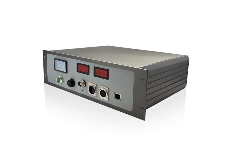
A project starts with a problem. A client needed an IP67-rated enclosure[^11] for a field instrument, fast. We combined a standard enclosure profile with custom CNC end plates[^12], delivering a validated prototype in under two weeks.
Case Study: The IP67 Field Instrument
Let me tell you about a project with an engineer, let's call him Jeff. He was developing a new field monitoring device and was in a tough spot. He needed a rugged, lightweight, and IP67-sealed enclosure, and his timeline was tight because he had to get demo units to key clients. Sourcing from multiple vendors was causing delays and finger-pointing. Jeff came to us with his CAD files and his problem. Instead of designing a fully custom box from scratch, which would be slow and expensive, we suggested a hybrid solution[^13]. We started with one of our standard extruded enclosure bodies, which we keep in stock. This immediately cut development time by 40%. The real customization happened on the front and rear panels. We used our CNC machines to create custom end plates with the exact cutouts he needed and a special groove for a silicone gasket. Within 24 hours, our engineers sent back a revised design with DFM feedback. Jeff approved, and we had a fully finished, IP67-validated prototype on its way to him in just nine business days. He was able to meet his deadline, and his project was a huge success.
| Project Phase | Timeline | Outcome |
|---|---|---|
| 1. Initial Consultation | Day 1 | Jeff explains needs; we propose a hybrid solution. |
| 2. DFM & Quote | Day 2 | Our engineers provide feedback; Jeff approves the design. |
| 3. Prototype Production | Day 3-9 | We machine, finish, and assemble the custom prototype. |
| 4. Delivery & Validation | Day 10-14 | Jeff receives the prototype, validates IP67 sealing and fit. |
Conclusion
Taking an enclosure from idea to reality is a clear, step-by-step process. A partnership built on communication and integrated manufacturing[^3] ensures your project succeeds on time and without surprises.
---

[^1]: Understanding collaborative design and DFM can enhance your product development process, ensuring efficiency and quality.
[^2]: Explore how rapid prototyping can save time and costs while improving product accuracy and validation.
[^3]: Learn how integrated manufacturing streamlines production, reduces errors, and enhances product quality.
[^4]: Discover the importance of secure logistics in ensuring safe and timely delivery of your products.
[^5]: A 3D CAD model is crucial for accurate manufacturing; find out how it can improve your design process.
[^6]: Understanding DFM can help you avoid costly design errors and improve manufacturability.
[^7]: CNC machining is vital for precision manufacturing; learn how it can enhance your product's quality.
[^8]: Explore various surface finishing techniques to improve the durability and aesthetics of your products.
[^9]: Anodizing can enhance the lifespan and appearance of your products; find out how it works.
[^10]: Silk-screening is essential for branding; learn how it can elevate your product's visual appeal.
[^11]: Understanding IP67 ratings is crucial for product durability; discover why it matters for your designs.
[^12]: Custom CNC end plates can enhance product functionality; learn about their manufacturing process.
[^13]: A hybrid solution can optimize your design process; explore how it combines standard and custom elements.