EMI Shielding Enclosure Design: Grounding Tips for Custom Aluminum Electronic Enclosures
Meta description: Learn how to specify a custom aluminum EMI shielding enclosure with grounding points, CNC cutouts, gasket design, and finish control for OEM electronics.
Why EMI Shielding Starts With the Enclosure
For industrial automation devices, IoT gateways, communication modules, power control units, and test instruments, the enclosure is more than a mechanical cover. It is part of the product's electromagnetic compatibility strategy.
A well-designed aluminum electronic enclosure can help reduce radiated noise, protect sensitive electronics from external interference, support grounding, and provide a stable structure for connectors and cable entries. A poorly specified enclosure can do the opposite. It may look correct in a sample review but create unexpected EMC test failures, unstable communication, sensor noise, or field reliability problems.
Many OEM buyers focus first on size, hole layout, color, and price. Those items matter, but for EMI-sensitive equipment, the purchasing specification should also define how the enclosure maintains conductive continuity. The most important question is simple:
Can the assembled enclosure behave as one controlled conductive system after machining, finishing, gasket installation, and final assembly?
If the answer is unclear, the project may face late-stage redesign.
What Makes Aluminum Useful for EMI Shielding?
Aluminum is widely used for custom electronic enclosures because it combines low weight, good machinability, corrosion resistance, thermal conductivity, and electrical conductivity. For many industrial and commercial electronics, aluminum provides a practical balance between shielding performance and manufacturability.
However, aluminum shielding performance is not determined by material alone. It depends on the complete enclosure system:
- Base material and wall thickness
- Cover and body overlap
- Screw spacing and clamping force
- Conductive contact surfaces
- Gasket type and compression
- Connector bonding
- Cable entry design
- Coating or anodizing thickness
- CNC cutout accuracy
- Final assembly quality
In other words, the enclosure is only as strong as its weakest electrical and mechanical connection.
6063 vs 6061 Aluminum for EMI-Sensitive Enclosures
Most custom aluminum electronic enclosures use 6000-series aluminum alloys. Two common options are 6063 and 6061. Both can be machined, anodized, and used in electronic housing applications, but they are not identical.
| Factor | 6063 Aluminum | 6061 Aluminum |
|---|---|---|
| Typical use | Extruded enclosure bodies, tube extrusion housings, visible profiles | CNC plates, stronger brackets, structural parts |
| Extrusion performance | Excellent for complex and smooth profiles | Good, but less ideal for very complex thin profiles |
| Surface finish | Strong choice for decorative anodizing and brushed finishes | Good, but surface may be less ideal for appearance-critical extrusion |
| Strength | Adequate for many electronic enclosures | Higher strength and rigidity |
| Machining | Good | Very good |
| Practical recommendation | Use for custom extrusion profiles, instrument shells, and IoT housings | Use where higher mechanical strength or heavy CNC processing is required |
For many industrial IoT enclosures, 6063 extrusion is a cost-effective base material because it supports custom cross-sections, integrated screw bosses, PCB slots, and heat-dissipation surfaces. For front plates, mounting brackets, or load-bearing structures, 6061 may be preferred when the design requires higher strength.
The buyer should not select alloy only by habit. The correct choice depends on profile complexity, machining volume, load requirements, surface finish, thermal needs, and batch cost.
The Hidden Problem: Anodizing Can Interrupt Grounding
Anodizing is one of the most common finishes for aluminum enclosures. It improves corrosion resistance, creates a stable appearance, and supports colors such as black, silver, blue, or custom tones. For B2B buyers, anodizing is often necessary because the enclosure must look professional and survive repeated handling.
But there is one important engineering detail:
Anodized aluminum surfaces are not reliable conductive contact surfaces.
The oxide layer is useful for protection, but it can weaken electrical contact between the cover, body, front panel, ground lug, or connector shell. If the buyer expects the enclosure to support EMI shielding or grounding, the drawing should identify which surfaces must remain conductive.
Practical Ways to Preserve Conductive Contact
- Mask grounding zones before anodizing. This keeps selected areas free from anodized coating.
- Machine contact pads after finishing. This exposes bare aluminum at defined grounding locations.
- Use conductive hardware. Serrated washers can help penetrate surface films when appropriate, but they should not replace a controlled grounding design.
- Specify ground symbols on drawings. Mark the required conductive zones in the 2D drawing so the supplier can quote and inspect them.
- Inspect continuity after assembly. A simple electrical continuity check between specified points can catch many finish-related errors before shipment.
For export OEM projects, the most reliable approach is to show grounding zones directly in the drawing package. This avoids relying on assumptions during quotation, sampling, and batch production.
Seams, Covers, and Screw Spacing
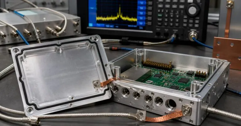
An aluminum box does not automatically function as a continuous shield. Gaps between the cover and body can allow electromagnetic leakage. Large seams, loose covers, uneven gasket compression, and wide screw spacing can reduce effectiveness.
For custom aluminum enclosures, the mechanical design should consider:
- Cover overlap length
- Flatness of the mating surface
- Screw spacing around the perimeter
- Gasket groove accuracy
- Burr removal after CNC machining
- Surface finish thickness at mating areas
- Whether the gasket is for environmental sealing, EMI continuity, or both
If the enclosure must meet both environmental protection and EMI requirements, buyers should clarify whether the gasket is only a silicone or EPDM sealing gasket, or whether a conductive EMI gasket is needed. A standard waterproof gasket may support IP sealing, but it may not provide electrical continuity across the seam.
Cable Entries and Connector Cutouts Are Critical
Many EMI problems appear around cable entries, not in the solid aluminum wall. Industrial gateways, PLC modules, routers, and test instruments often require multiple openings:
- M12 connectors
- SMA or antenna ports
- RJ45 ports
- USB ports
- D-sub connectors
- Cable glands
- Power terminals
- Display windows
- Ventilation openings
Every cutout changes the shielding structure. The goal is not to avoid openings, because the device needs interfaces. The goal is to control them.
CNC Cutout Recommendations for Buyers
When preparing an RFQ, include:
- A 2D drawing with hole size and tolerance. Do not rely only on a rendered 3D image.
- Connector datasheets or panel-mount drawings. This helps confirm clearance, nut space, and gasket seating.
- Critical-to-function dimensions. Mark which holes affect sealing, grounding, or connector alignment.
- Burr and edge requirements. Sharp burrs can damage gaskets and cable insulation.
- Finish restrictions around connector shells. Define whether connector contact areas must remain bare or conductive.
PUMAYCASE can support custom CNC cutouts for front panels, rear panels, side walls, and extrusion bodies. For connector-heavy designs, early drawing review can prevent avoidable machining cost and assembly problems.
Grounding Design: What to Specify in the Drawing
A good grounding specification is simple, visible, and inspectable. It should tell the enclosure supplier exactly where electrical contact is required.
Recommended Grounding Details
| Design Item | What to Define | Why It Matters |
|---|---|---|
| Ground stud or screw point | Position, thread, bare-metal contact area, hardware type | Provides a controlled connection between PCB, cable shield, and enclosure |
| Conductive cover contact | Masked strip, machined pad, or conductive gasket location | Maintains continuity across the enclosure seam |
| Connector shell bonding | Bare metal around connector hole or conductive washer requirement | Prevents floating connector shells |
| PCB mounting bosses | Whether standoffs are isolated or bonded | Avoids accidental ground loops or missing chassis ground |
| Surface finish note | Anodized, powder coated, masked, or post-machined area | Prevents insulating coatings from blocking contact |
| Inspection method | Continuity test point list | Makes batch quality easier to verify |
For many OEM projects, the supplier does not need the full EMC test plan. But the supplier does need to know which enclosure features are part of the grounding path.
Balancing EMI Shielding, IP Protection, and Heat Dissipation
Industrial and IoT buyers often need multiple performance targets in one enclosure:
- EMI shielding
- IP65, IP67, or higher environmental sealing
- Heat dissipation
- Outdoor corrosion resistance
- Brand appearance
- Wall or DIN rail mounting
- Fast sample delivery
- Controlled batch cost
These requirements can conflict if they are not coordinated.
For example, ventilation openings help thermal performance but can reduce shielding and water resistance. Thick anodizing improves surface durability but can reduce grounding reliability. A soft sealing gasket improves waterproofing but may not support conductive continuity. A very small enclosure reduces cost but can concentrate heat and make cable routing difficult.
The best enclosure design is not the one with the most features. It is the one where each feature supports the product's real operating environment.
Practical Engineering Trade-Offs
| Requirement | Possible Conflict | Practical Solution |
|---|---|---|
| IP sealing | Gasket may isolate cover from body | Add defined conductive pads or conductive gasket sections |
| Anodized finish | Coating can interrupt ground path | Mask or machine grounding zones |
| Heat dissipation | Fins or vents may affect sealing or shielding | Use external fins, thicker heat-spreading walls, or sealed thermal paths |
| Many connectors | Large openings weaken enclosure continuity | Group connectors, bond shells, and control cutout tolerances |
| Low unit cost | Overly complex machining increases price | Use extrusion features, standard screw locations, and shared panel designs |
Procurement Checklist for a Custom EMI Shielding Enclosure
Before requesting a quotation, buyers should prepare a clear technical package. This saves time and improves quote accuracy.
RFQ Package
- 3D file: STEP is preferred for structure review.
- 2D drawing: PDF with dimensions, tolerances, material, finish, and inspection notes.
- Connector drawings: datasheets for panel-mounted components.
- Finish requirement: color, anodizing type, brushing direction, logo method, and masked zones.
- Grounding requirement: ground points, conductive contact areas, and continuity inspection points.
- Sealing requirement: target IP level, gasket material, groove details, and screw spacing.
- Quantity plan: prototype quantity, pilot batch, annual estimate, and repeat-order expectation.
- Branding requirement: laser marking, silk screen, or custom logo position.
- Packaging requirement: scratch prevention, export carton, and labeling.
Sample Approval Checklist
During sample approval, inspect:
- CNC hole position and connector fit.
- Cover flatness and seam consistency.
- Gasket seating and compression.
- Anodizing color and surface defects.
- Conductive grounding zones.
- Thread quality and screw engagement.
- Burr removal around all openings.
- Electrical continuity between specified points.
- Assembly clearance for PCB, cables, and heat-generating components.
- Packaging protection for finished surfaces.
This checklist turns the enclosure from a visual sample into an engineering-approved component.
How PUMAYCASE Supports OEM Buyers
PUMAYCASE manufactures custom aluminum electronic enclosures, extrusion enclosures, instrument chassis, 19 inch rackmount chassis, amplifier boxes, and CNC-machined aluminum parts for B2B buyers.
For EMI-sensitive projects, PUMAYCASE can support:
- Aluminum extrusion enclosure design
- CNC machined front and rear panels
- Custom connector and display cutouts
- Grounding pad and contact zone planning
- Anodizing, brushing, laser marking, and silk screen printing
- Silicone or EPDM gasket integration
- OEM/ODM customization
- Sample and small-batch production
- Batch inspection for repeat orders
For industrial automation, IoT hardware, communication equipment, test instruments, and control modules, the most efficient process is to involve the enclosure supplier before the design is frozen. Early enclosure review can reduce rework, protect the schedule, and improve batch consistency.
Conclusion
An EMI shielding enclosure is not only a material choice. It is a coordinated system of aluminum alloy, mechanical contact, surface finish, CNC accuracy, gasket design, connector bonding, and inspection control.
For OEM buyers, the most important step is to make the grounding and shielding requirements visible in the drawing package. Define the conductive areas. Identify the ground points. Clarify finish restrictions. Provide connector drawings. Confirm sample inspection criteria before batch production.
When these details are controlled early, a custom aluminum electronic enclosure can support not only product appearance and protection, but also EMC readiness, assembly efficiency, and long-term supply stability.
Need a custom aluminum EMI shielding enclosure for an industrial or IoT project? Send your drawings, connector list, target finish, and sample quantity to PUMAYCASE for engineering review and quotation.