Your detailed CAD model is done, but now you face hours of creating separate drawings and BOMs. A single design change creates a cascade of updates, risking costly manufacturing errors.
Yes, the digital thread1 connects design to production using a single, rich 3D file. This file, containing all product data (PMI), enables automated CAD-CAM integration2 for machines and provides complete MES traceability3, creating a seamless flow from your initial design to the finished part.
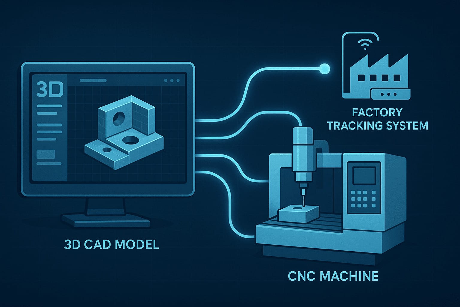 "The Digital Thread from CAD to Factory Floor"
I remember the old days clearly. An engineer would email us a 3D model... and then a 27-page PDF of 2D drawings. My job was to manually compare the two, looking for discrepancies. If a hole was 5mm in the drawing but 5.1mm in the model, which was correct? A phone call, an email chain, a 24-hour delay. This back-and-forth was the standard way of doing things. The digital thread is changing all of that. It’s about making the 3D model the single source of truth, eliminating the confusion and delays I used to fight every single day.
How Can a 3D File Replace a 2D Drawing?
You've finished the 3D model, but now must create separate 2D drawings for critical tolerances. This redundant work invites errors, where a mismatch between files can lead to scrap parts.
A 3D model can replace a 2D drawing by using formats like STEP AP2424. These aren't just shapes; they contain Product Manufacturing Information5 (PMI) like tolerances, finishes, and notes embedded directly on the model, making the 3D file the single source of truth.
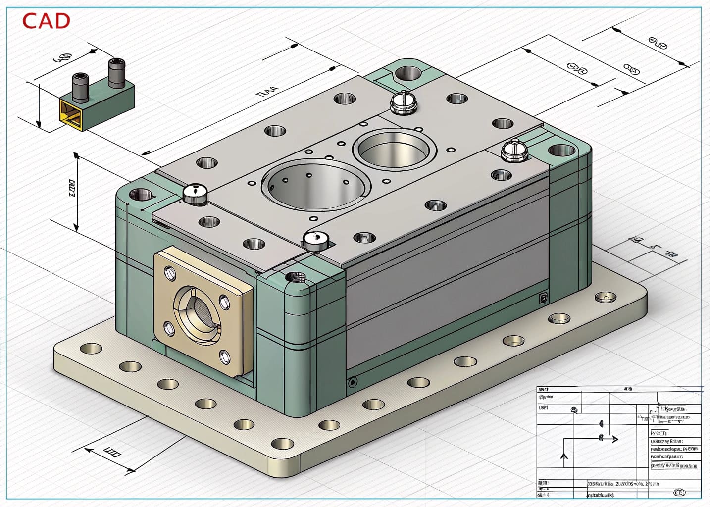 "3D Model with Embedded PMI Data"
The traditional method separates "what it looks like" (the 3D model) from "how to make it" (the 2D drawing). This is a broken system. The digital thread fixes this by embedding "how to make it" directly into the 3D model file. We call this Product and Manufacturing Information, or PMI. Think of it like digital sticky notes attached to every surface of your model. Modern file formats, especially STEP AP242, are designed to carry this rich data. So instead of a drawing telling me a hole needs a specific tolerance, the hole itself has that tolerance data attached to it within the 3D space. This eliminates any chance of a mismatch between documents and is a foundational step towards true Industry 4.06 automation, where machines can read the design intent directly.
The Old Way vs. The Digital Thread Way
| Aspect | Traditional Workflow | Digital Thread Workflow |
|---|---|---|
| Primary File | 2D Drawing (PDF) | 3D Model with PMI (STEP AP242) |
| Data Source | Multiple (3D, 2D, BOM) | Single Source of Truth |
| Risk of Error | High (manual interpretation) | Low (machine readable) |
| Efficiency | Low (redundant work) | High (streamlined) |
Can Software Really Automate CNC Programming?
Your part is ready for machining, but a programmer is manually clicking every surface to create toolpaths. This process is slow, costly, and introduces the risk of human error.
Yes, through advanced CAD-CAM integration. The CAM software reads the manufacturing data (PMI) embedded in your 3D file. It automatically recognizes features like holes and pockets, selects the correct tools, and generates the machine G-code, drastically reducing manual programming time and errors.
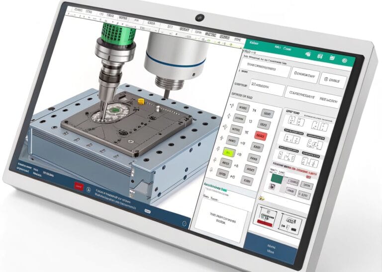
 "Automated Toolpath Generation with CAD-CAM Integration"
When we receive a "smart" 3D model rich with PMI, our CAD-CAM integration software gets to work immediately. It's no longer just a dumb shape; the software can now perform "feature recognition7." It doesn't just see a cylinder; it sees a "tapped hole, M3 thread, 8mm deep." It doesn't just see a flat face; it sees a "surface requiring a 0.8 Ra finish." Because the software understands the intent, it can automatically apply pre-defined machining strategies. It knows that an M3 hole requires a specific drill and tap. It knows a smooth finish requires a slower final pass with a specific tool. This automates the most time-consuming part of CNC programming, ensuring that the design specifications are met perfectly and consistently, every single time. The engineer's design intent is passed directly to the machine.
From Design Intent to Machine Instructions
| PMI Data in Model | CAM Software Action | Result |
|---|---|---|
| Hole with +/- 0.05mm tolerance | Selects reaming tool after drilling. | Precise hole diameter. |
| M4 Thread Callout | Selects M4 tapping cycle. | Correctly threaded hole. |
| Ra 1.6 Surface Finish Symbol | Adds a final, slow finishing pass. | Smooth, specified surface. |
| Pocket Feature | Selects roughing and finishing strategy. | Efficient material removal. |
How Does the Digital Thread Prevent Lost Parts in the Factory?
A customer calls for an order update, and you have no idea where it is. This manual searching is slow, and a lost part means a missed deadline and a costly remake.
The digital thread assigns a unique ID to each part, born from the original design file. A Manufacturing Execution System (MES) uses this ID for MES traceability3. Each time the part is scanned at a new workstation, its status is updated, creating a live digital history.
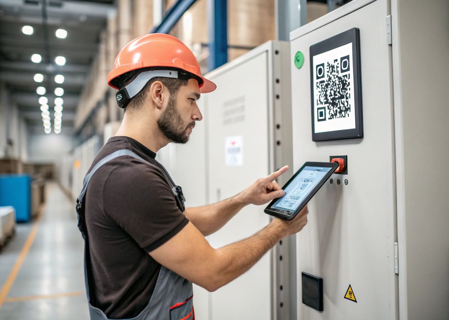 "Real-time MES Traceability in Action"
The digital thread connects the physical part to its "digital twin8." When we start a job from a smart 3D model, our system automatically generates a unique identifier, often a QR code, which we laser-etch directly onto the part. This code is the part's passport. It is linked to the original file and all its PMI data in our Manufacturing Execution System (MES). As the physical part moves through the factory, its passport gets stamped. A quick scan at the CNC machine updates its status to "Machining Complete." Another scan at the anodizing station updates it to "Anodizing." This gives us complete, real-time MES traceability. If a customer asks where their order is, I can tell them its exact location and status in seconds. More importantly, if a quality issue arises, we have a complete digital record of its entire journey.
A Part's Journey Through the MES
| Workstation | Scan Action | MES Status Update | Data Attached |
|---|---|---|---|
| CNC Machining | Operator scans QR code. | Status: "Machined" | Cycle time, operator ID. |
| Deburring | Operator scans QR code. | Status: "Deburred" | Time spent. |
| Anodizing | Operator scans QR code. | Status: "Anodizing" | Batch number, color spec. |
| Final QC | Inspector scans QR code. | Status: "Approved" | Inspection report, measurements. |
Conclusion
The digital thread links a smart 3D model to the factory floor. It enables automated CAD-CAM integration and real-time MES traceability, reducing errors and delivering parts with precision and speed.
Explore how the digital thread revolutionizes manufacturing by connecting design to production seamlessly. ↩
Learn how CAD-CAM integration automates processes, reducing errors and saving time in production. ↩
Discover the significance of MES traceability in tracking parts and ensuring quality in manufacturing. ↩ ↩
Find out how STEP AP242 format improves data sharing and reduces errors in manufacturing workflows. ↩
Understand how PMI enhances the accuracy of manufacturing by embedding critical data in 3D models. ↩
Explore the principles of Industry 4.0 and its transformative effects on modern manufacturing practices. ↩
Discover how feature recognition enhances CAD software capabilities, improving design and manufacturing processes. ↩
Explore the concept of a digital twin and its role in optimizing manufacturing operations. ↩