
Custom Aluminum Enclosure Tolerances: How Can Engineers Prevent Assembly Problems?
Small tolerance errors can stop assembly. They also delay waterproof tests and connector fitting. I prevent this by checking enclosure, PCB, gasket, and CNC details together.
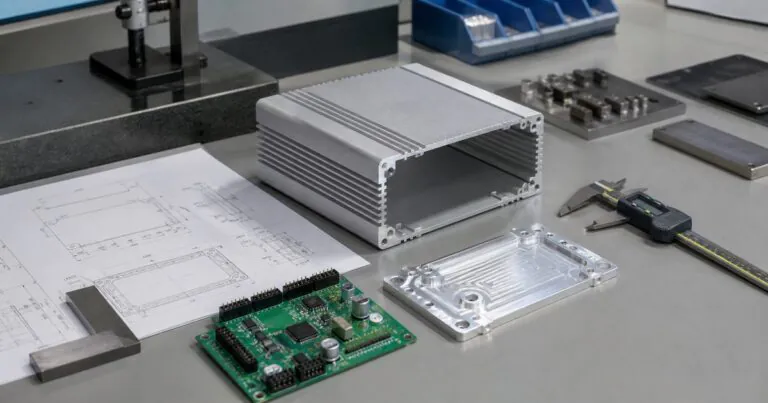
Custom aluminum enclosure tolerances should be reviewed as an assembly system, not as separate part dimensions. Engineers should define functional dimensions, connector clearances, gasket compression, screw positions, surface finish effects, and inspection datums before CNC machining starts.
%custom aluminum enclosure tolerances for PCB assembly and CNC machined end plates
I studied how strong enclosure manufacturers educate engineers through practical design topics. The best articles do not only explain a material or process. They help an engineer avoid a real project delay. This article follows that direction, but I focus on the problems I often see at PUMAYCASE when engineers design compact aluminum electronic enclosures for IoT, automation, outdoor sensing, and control devices.
Table of contents
- 1. Why Do Custom Aluminum Enclosure Tolerances Matter Before CNC Machining?
- 2. How Should Engineers Control Tolerance Stack in Waterproof Aluminum Enclosures?
- 3. What Tolerance Details Affect Heat Dissipation and Surface Treatment?
- 4. How Can Engineers Send Better Drawings to Reduce Lead Time?
- Conclusion
1. Why Do Custom Aluminum Enclosure Tolerances Matter Before CNC Machining?
A drawing can look correct but still fail assembly. This creates urgent rework and pressure. A tolerance review before CNC machining reduces this risk.
Custom aluminum enclosure tolerances matter because each dimension affects another part. PCB height, connector position, end plate cutouts, extrusion length, screw holes, gasket grooves, and anodizing thickness all influence final fit and protection.
%CNC machined aluminum enclosure end plate with connector tolerance inspection
Practical Engineering Notes
When I review a custom aluminum enclosure drawing, I do not check only the outside size. I first ask how the device will be assembled. A compact IoT controller may have a PCB, terminal block, antenna, heat pad, LED light pipe, cable gland, and silicone gasket in one small body. Each item may look simple. But when all parts come together, small deviations can become a serious assembly issue.
For example, a connector cutout may be correct on the 2D drawing, but the PCB may sit 0.5 mm higher after standoffs and soldered components are installed. In this case, the connector does not sit in the center of the opening. The engineer may think the end plate was machined wrong. But the real problem is often the full tolerance stack.
I suggest engineers mark functional dimensions clearly. A cosmetic outside length may allow a wider tolerance. A connector centerline usually needs tighter control. A screw hole that locates the PCB should be treated differently from a simple ventilation slot. This is also why clear 2D and 3D files are important when you send a project to custom aluminum enclosure solutions.
| Area | Common Tolerance Risk | Better Design Check |
|---|---|---|
| PCB mounting holes | Board cannot align with standoffs | Define datum from one fixed hole and one slot |
| Connector cutouts | Connector rubs edge or looks off-center | Check PCB stack height and connector body size |
| End plate screw holes | End plate cannot close smoothly | Match extrusion thread position before machining |
| Gasket groove | Seal is too loose or too compressed | Define gasket section and compression target |
| Anodized surface | Tight sliding fit becomes too tight | Leave allowance for surface treatment |
I like using one fixed datum hole and one slotted hole for PCB mounting when the layout allows it. This reduces stress from small machining and board fabrication differences. Datum thinking is not only for large mechanical parts. NIST explains datum concepts as reference origins for part features, and this same logic helps enclosure teams keep inspection consistent in real production. You can read more about datum reference concepts from NIST datum system research.
2. How Should Engineers Control Tolerance Stack in Waterproof Aluminum Enclosures?
Waterproof failure often starts with small gaps. These gaps are hard to see during design. Engineers should control gasket pressure, flatness, screw spacing, and cable gland fit.
To control tolerance stack in waterproof aluminum enclosures, define the sealing path first. Then check gasket groove depth, compression, end plate flatness, screw torque, machining burrs, coating thickness, and cable entry position together.
%waterproof aluminum enclosure gasket groove tolerance and IP67 sealing design
Practical Engineering Notes
A waterproof enclosure is not waterproof because one part has a good material. It becomes waterproof because many small details work together. The gasket must have the right compression. The end plate must be flat enough. The screws must apply pressure evenly. The machined groove must not cut the gasket. The cable gland must match the cable diameter.
I often see engineers focus only on IP67 or IP68 as a target. That target is useful, but it is not a design by itself. The enclosure still needs a clear sealing structure. NI explains that enclosure ratings help match a system to its environment, including IP and NEMA protection levels. This is a good reminder that the rating should follow the actual installation condition, not only a marketing requirement. Here is a useful reference from NI about selecting an enclosure.
For outdoor sensors, I usually ask several questions before we machine the first sample. Will the device face rain only, or temporary water immersion? Will the cable leave from the bottom or side? Will the customer open the enclosure many times during installation? Will the gasket be replaced? These details change the tolerance plan.
| Waterproof Detail | What Can Go Wrong | PUMAYCASE Design Suggestion |
|---|---|---|
| Gasket groove depth | Low compression causes leakage | Confirm gasket hardness and compression range |
| Screw spacing | Uneven pressure creates corner gaps | Add screws near corners and long edges |
| End plate flatness | Seal line is not uniform | Avoid thin weak plates on large openings |
| Cable gland hole | Wrong hole size damages seal | Confirm thread standard and cable diameter |
| Anodizing | Surface change affects groove fit | Confirm finish before final tolerance lock |
For waterproof aluminum enclosures, I prefer to review the sealing path before the outside shape is finalized. If the sealing path is added too late, the engineer may need to move holes, change screw positions, or thicken the end plate. That costs more time than a careful early check.
3. What Tolerance Details Affect Heat Dissipation and Surface Treatment?
Heat problems can become worse after assembly. Surface treatment can also change fit. Engineers should connect thermal design, CNC machining, and anodizing choices early.
Tolerance details affect heat dissipation when they change contact pressure, wall thickness, heat pad compression, or surface flatness. Anodizing and coatings also add surface layers that may affect tight fits and grounding paths.
%anodized custom aluminum enclosure with heat pad contact and CNC tolerance control
Practical Engineering Notes
Aluminum is popular for electronic enclosures because it is light, strong enough for many devices, easy to machine, and helpful for heat spreading. Engineering Toolbox lists aluminum among materials with high thermal conductivity compared with many plastics and non-metal materials. This is one reason engineers choose aluminum housings for compact power modules and edge devices. You can check general conductivity data from Engineering Toolbox thermal conductivity tables.
But aluminum material alone does not solve heat. The heat source must touch the enclosure through a controlled path. If the PCB sits too low, the thermal pad may not compress enough. If the enclosure inner wall is not flat enough, contact resistance increases. If the heat pad is too thick, it can push the PCB and connector out of position. This is another tolerance stack problem, but now it affects both assembly and temperature.
Surface treatment also matters. Anodizing improves corrosion resistance and appearance, but it changes the surface. In most enclosure projects, the effect is small. But for sliding parts, press-fit parts, grounding points, or tight connector windows, engineers should include surface treatment in the design review. At PUMAYCASE, I like to confirm finish before final CNC programming because a late color or finish change may affect both appearance and fit.
| Design Area | Thermal or Finish Risk | What to Confirm |
|---|---|---|
| Heat pad contact | Too loose or too compressed | Gap between component and inner wall |
| Wall thickness | Heat does not spread well | Minimum wall and local boss design |
| Anodized parts | Tight fit changes after finish | Final color, finish type, and tolerance allowance |
| Grounding point | Insulation blocks contact | Masking, bare metal area, or conductive treatment |
| Laser marking | Mark position conflicts with features | Final panel layout before production |
For CNC aluminum enclosure machining, I ask customers to send the PCB 3D model when possible. The model helps us check collision, connector height, heat pad space, and screw boss position before machining. This does not remove all risk, but it catches many problems before money is spent on the first sample.
4. How Can Engineers Send Better Drawings to Reduce Lead Time?
Unclear drawings slow down supplier feedback. They also create wrong assumptions. Engineers can reduce lead time by sending complete files and clear technical priorities.
Engineers can reduce lead time by sending 2D drawings, 3D models, material notes, finish requirements, IP target, tolerance priorities, quantity, and assembly purpose together. Clear information helps suppliers review manufacturability faster.
%engineer drawing package for custom aluminum enclosure prototype and lead time control
Practical Engineering Notes
Fast customization does not only depend on the factory. It also depends on how clear the project information is. When Jeff sends a complete drawing package, I can ask better questions and give faster engineering feedback. When I receive only a simple sketch, I can still help, but more details must be confirmed before CNC machining.
A good enclosure RFQ does not need to be perfect. It should explain what matters most. For example, if the enclosure is for an outdoor smart sensor, the IP rating and cable gland position may be more important than a cosmetic chamfer. If it is for an edge AI controller, heat contact and connector alignment may be more important. If it is for a handheld instrument, surface finish and label position may affect the user experience.
| File or Note | Why It Helps | Example |
|---|---|---|
| 3D model | Checks collision and assembly fit | STEP file of PCB and enclosure |
| 2D drawing | Defines tolerances and inspection points | PDF with critical dimensions marked |
| Finish note | Avoids late surface changes | Black anodized, laser marking, no coating on grounding area |
| IP target | Guides sealing design | IP67 outdoor rain and temporary splash |
| Quantity | Matches process and cost plan | 20 prototypes, then 500 pcs batch |
| Schedule | Helps plan machining and finishing | Need first samples in 10 working days |
I also suggest marking critical dimensions with a note such as “connector fit critical” or “PCB datum hole.” This simple note tells the supplier where to focus inspection. It also helps avoid wasting time on dimensions that do not affect function.
At PUMAYCASE, our goal is not only to make an enclosure. I want to help engineers protect their schedule. Clear files, fast feedback, and practical tolerance control make the difference between a prototype that moves forward and a prototype that comes back for avoidable rework.
Conclusion
Custom aluminum enclosure tolerances are assembly decisions. When engineers check fit, sealing, heat, finish, and drawings together, they reduce prototype risk and lead time.