
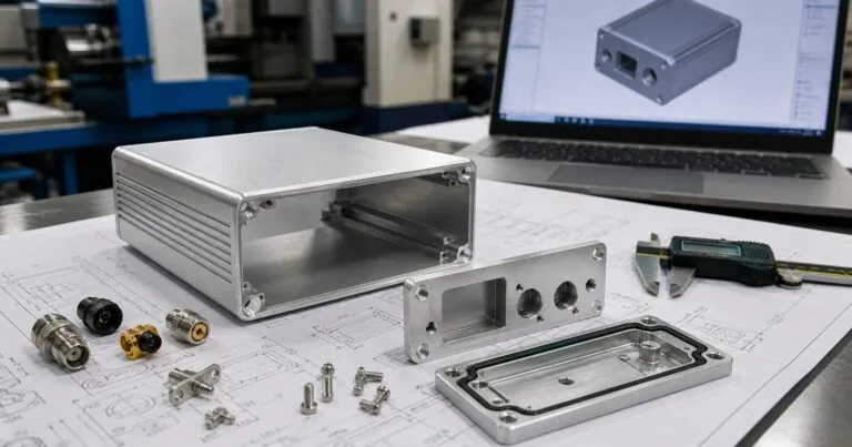
A CNC machined aluminum enclosure can fit its PCB and connectors only when the product definition communicates the right geometry and functional limits. A model that looks complete on screen may still leave a supplier guessing about datums, tolerances, threads, corner radii, finish, or the configuration to inspect.
OEM buyers should provide a coordinated drawing package that distinguishes design intent from manufacturing suggestions. The most useful package combines controlled 2D requirements, 3D geometry, interface data, and an inspection plan, then keeps them aligned through sampling and repeat orders.
Which Files Belong in a Controlled Drawing Package?
A controlled package usually needs a dimensioned 2D drawing plus 3D data when available. Each file has a different purpose, so the RFQ should identify the governing revision and how conflicts will be resolved.[1]
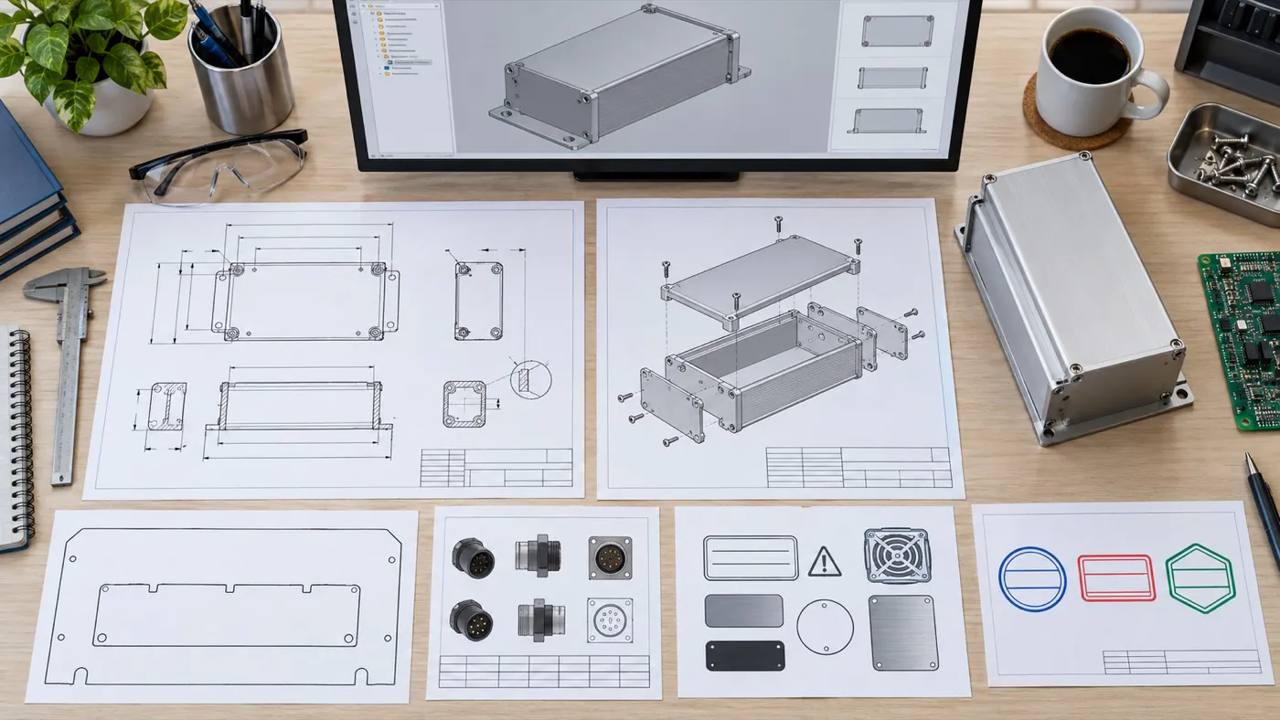
Keep models, drawings, artwork, and revision identifiers consistent in one controlled package.
| File | Main purpose | Control to include |
|---|---|---|
| PDF drawing | Dimensions, datums, tolerances, notes, and acceptance requirements | Part number, revision, units, and approval status |
| STEP/STP model | Geometry, interference review, and machining reference | Revision matching the 2D drawing |
| DXF/DWG profile | Panel openings or flat geometry | Scale, origin, units, and revision |
| Component datasheet | Connector, gland, switch, display, or vent interface | Exact manufacturer and part number |
| Vector artwork | Logo, legends, symbols, and identification | Size, color, position, and revision |
- Name the governing document. State whether the 2D drawing, model, or another specification controls a disputed feature.
- Use one part number per configuration. Different panel layouts or finishes should not share an ambiguous release package.
- Match revisions across files. A changed connector cutout in the PDF must also appear in the model and DXF used for review.
- List open items separately. A provisional dimension should not look like a production-approved requirement.
Statement: A detailed STEP model automatically defines every manufacturing and inspection requirement.
Answer: False
Explanation: The model communicates geometry, while datums, tolerances, notes, finish, and acceptance criteria still need controlled definition.
How Should Datums and Dimensions Communicate Design Intent?
Datums should follow the surfaces and axes that locate the enclosure in the finished product. Consistent references allow design, CNC programming, and inspection to discuss the same relationships; ASME Y14.5 provides a recognized language for dimensioning and tolerancing.[1]
| Functional relationship | Possible reference strategy | Reason to control it |
|---|---|---|
| Front connector to PCB | Locate connector center from panel and PCB mounting datums | Preserves mating alignment |
| Lid to enclosure body | Reference the seating or sealing interface | Controls closure relationship |
| External mounting holes | Locate from the mounting face and product centerline | Preserves equipment installation |
| Display window to bezel | Locate the opening from visible-face datums | Controls alignment and appearance |
- Choose functional datums. A convenient raw edge may be a poor reference if it does not locate the PCB, connector, lid, or machine mount.
- Avoid uncontrolled dimension chains. Accumulated variation can shift the final connector or hole pattern even when each local dimension is within tolerance.
- Dimension feature relationships. Center-to-center or datum-based locations often communicate alignment more clearly than unrelated edge dimensions.
- Show the required coordinate system. DXF origins, model axes, and drawing datums should not contradict one another.
The drawing should express the result the product needs. The manufacturer can then review whether the proposed datum and inspection method are practical for the selected extrusion, die-cast body, panel, or fully machined part.
Statement: Any convenient enclosure edge is equally suitable as the primary datum.
Answer: False
Explanation: A datum should support the functional relationships and a repeatable manufacturing and inspection setup.
Which Cutouts and Secondary Features Need Definition?
Every opening should be defined as a complete interface rather than a nominal shape. Panel thickness, connector hardware, tool radius, seal, and customer assembly access may change the required geometry.
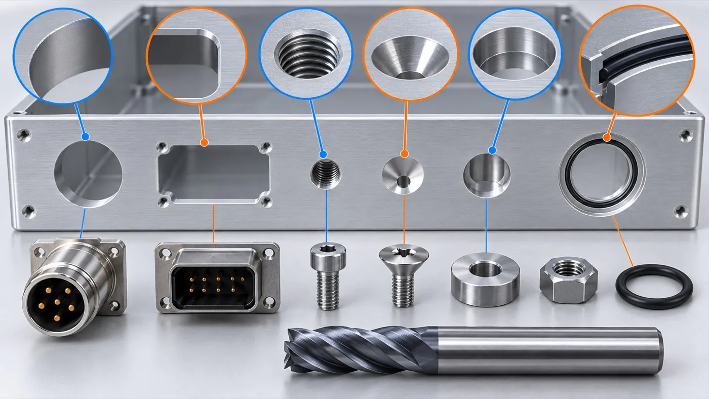
Define each machined feature with its size, location, purpose, and applicable notes.
| Feature | Drawing information | Related input |
|---|---|---|
| Circular opening | Diameter, location, side, and any thread or counterbore | Component body, washer, nut, and cable clearance |
| Rectangular cutout | Width, height, corner radii, location, and edge condition | Connector flange, plug overmold, or display window |
| Threaded hole | Thread designation, depth, entry side, and quantity | Fastener length and engagement need |
| Countersink/counterbore | Diameter, angle or depth, and side | Fastener head and surface requirement |
| Sealing land | Extent, flatness requirement if functional, and prohibited marks | Gasket or sealing-component data |
- Attach the exact component datasheet. Generic connector names do not define a cutout or mounting stack.
- State the machining side. A feature may be inaccessible or create a different burr direction when approached from the opposite face.
- Allow for cutter geometry. Internal corners cannot be assumed perfectly sharp; specify an acceptable radius or relief based on the mating part.
- Include installation space. Tools, nuts, washers, cables, and mating plugs require room beyond the visible opening.
If an interface must support ingress protection, the drawing package should identify the installed component, seal arrangement, mounting direction, and verification scope. A machined opening changes the finished enclosure configuration.
Statement: A connector catalog outline alone is enough to release its enclosure cutout.
Answer: False
Explanation: The installed interface can also depend on panel thickness, hardware, seal, tool access, corner radius, and cable clearance.
How Should Tolerances Follow Function and Process?
Tolerances should control fit, alignment, sealing, thermal contact, or interchangeability. Applying the same tight tolerance to every dimension can add manufacturing and inspection effort without improving the product.
| Dimension category | Functional question | Drawing approach |
|---|---|---|
| Connector or display location | What misalignment can the mating parts accept? | Define the position relative to functional datums |
| PCB mounting pattern | How much combined variation permits installation? | Evaluate hole, standoff, and board tolerances together |
| Sealing or thermal face | What form and contact condition does the design require? | Specify only the controlled area and inspection basis |
| General envelope | Which limits affect equipment fit or adjacent parts? | Apply appropriate general or explicit limits |
- Derive limits from an interface. Use connector clearance, screw pattern, gasket contact, or thermal-stack needs to justify the tolerance.
- Review the tolerance stack. Include PCB fabrication, component placement, enclosure features, coatings, and customer assembly where relevant.
- Separate critical from general dimensions. This tells the supplier where process control and inspection effort matter most.
- Agree on measurement. Datum setup, gauge, sampling, and before-or-after-finish condition can change how a requirement is interpreted.
PUMAYCASE cannot set a universal CNC tolerance without reviewing geometry, material, tool access, surface treatment, quantity, and inspection method. The drawing should invite manufacturability feedback where the required limit is not yet proven.
Statement: Tighter tolerances on every dimension always create a better enclosure.
Answer: False
Explanation: A tolerance adds value when it protects function; unnecessary tight limits can add process and inspection burden.
What Finish, Sealing, and Thermal Notes Belong on the Drawing?
Functional surface notes should be defined before machining and finishing are quoted. Coatings, masking, gasket paths, and thermal contact areas can interact with dimensions and inspection.

Use functional references and project-specific notes to connect geometry with finish and interface requirements.
| Drawing zone | Information to define | Verification question |
|---|---|---|
| Cosmetic surface | Finish process, color/texture reference, and visible class | Which lighting and sample define acceptance? |
| Electrical contact | Masking or post-finish contact requirement | How will continuity be validated in the customer’s product? |
| Thermal interface | Contact area and functional flatness/finish requirement | Which component, pad, and load create the stack? |
| Sealing interface | Gasket or seal part, contact path, openings, and closure configuration | What complete configuration must be tested? |
- State whether dimensions apply before or after finish. Coating or anodizing can matter at a close-fitting feature.
- Mark protected areas. Cosmetic treatment, engraving, burrs, or scratches should not enter a controlled seal or contact zone.
- Define the full thermal stack. The enclosure material alone does not guarantee component temperature or system performance.
- Connect IP notes to the finished configuration. IEC 60529 classifies degrees of protection provided by enclosures, but the project still needs a defined configuration and verification plan.[2]
PUMAYCASE can support brushing, sandblasting, anodizing, powder coating, silk screen printing, and laser marking as applicable. The drawing should state the intended combination and acceptance reference; it should not assume every process combination is suitable.
Statement: Specifying an IP target on a drawing proves that the customized device has passed that rating.
Answer: False
Explanation: A target guides design and verification; the actual result depends on the complete tested configuration and agreed criteria.
How Should Drawings Support Sample Inspection and Revision Control?
The released drawing should make sample approval repeatable. Engineering and procurement need to know which characteristics were checked, which deviations were accepted, and which revision becomes the baseline for trial production and repeat orders.
| Control record | Content | Later use |
|---|---|---|
| Sample inspection report | Critical dimensions, method, result, and drawing revision | Confirms measurable requirements |
| Fit and appearance approval | Approved PCB/interfaces, photos or notes, and finish reference | Records customer validation decisions |
| Deviation record | Feature, reason, quantity or duration, and approval | Prevents a temporary exception becoming permanent |
| Revision history | Changed features, date, and approval | Keeps repeat orders on the correct baseline |
- Select inspection points by risk. Focus on interfaces, mounting, sealing, contact areas, and visible features that affect product acceptance.
- Record the measurement setup. A result without datum and method information may not be reproducible.
- Close sample comments into the drawing. Email approval should lead to a controlled revision when it changes a requirement.
- Require review for substitutions. A connector, gasket, profile, or finish change can alter dimensions or validation assumptions.
PUMAYCASE supplies customized enclosures and related aluminum parts; the customer installs the PCB and electronics. Fit checks, functional tests, certification, and final-device performance remain separate responsibilities unless a specific enclosure inspection item is agreed for the project.
What Drawing Checklist Should Accompany the RFQ?
The final checklist should make omissions visible before a supplier quotes or machines a sample. Keep it short enough that engineering, purchasing, and quality teams will use it.
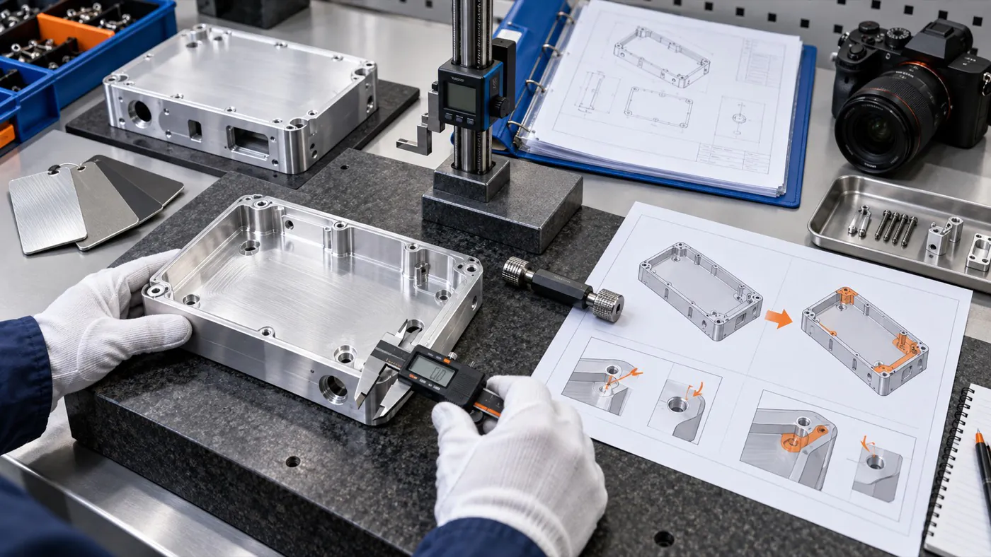
Compare the sample with the released drawing and record corrections before repeat production.
- Identification: Part number, revision, units, material or starting enclosure, and governing file.
- Geometry: Functional datums, controlled dimensions, cutouts, threads, radii, and mounting relationships.
- Interfaces: PCB envelope, connector datasheets, seals, thermal contacts, and customer assembly access.
- Production controls: Finish, marking, visible surfaces, inspection points, sample purpose, quantity, packaging, and open questions.
An existing aluminum profile or standard enclosure should be assessed first when its section, length range, closure, and interfaces fit the product. Necessary CNC machining, surface treatment, and marking can then be defined; if the base design does not fit, tooling or another manufacturing route needs evaluation.
Conclusion
OEM buyers should prepare CNC machined aluminum enclosure drawings as a controlled product definition: coordinated 2D and 3D files, functional datums, complete interface features, justified tolerances, finish and sealing notes, and a revision-based inspection plan. This gives the supplier enough information to evaluate machining without inventing requirements and gives the buyer a stable baseline for samples and repeat orders. For a drawing review, provide the PDF and STEP files, PCB envelope, connector datasheets, target quantity, finish, and the open items that still require validation.
References
- ASME, “Y14.5 – Dimensioning and Tolerancing,” https://www.asme.org/codes-standards/find-codes-standards/y14-5-dimensioning-tolerancing
- International Electrotechnical Commission, “IEC 60529: Degrees of protection provided by enclosures (IP Code),” https://webstore.iec.ch/en/publication/2452