
CNC Machined Aluminum Enclosure Connector Fit: How Can Engineers Avoid Prototype Delays?
Connector fit looks simple, but small tolerance mistakes can stop assembly. When prototypes fail, schedules slip. A CNC machined aluminum enclosure connector fit plan prevents this.
A CNC machined aluminum enclosure connector fit plan should define connector datasheets, cutout dimensions, edge clearance, gasket compression, screw position, surface finish, and inspection points before machining starts.
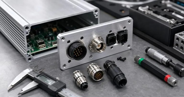
I often see this problem when a product team moves from a 3D concept to a real enclosure sample. The PCB is ready. The connector is selected. The cable is ordered. But the end plate opening is too tight, the nut cannot turn, or the waterproof connector gasket sits on an anodized edge with a burr. In this article, I will explain how I help engineers reduce these risks before CNC machining starts.
How Should Engineers Define Connector Cutouts Before CNC Machining?
Connector drawings are often incomplete, and enclosure panels leave little space. This creates rework. A clear cutout table helps the supplier machine the panel correctly.
Engineers should define each connector cutout with nominal size, tolerance, corner radius, panel thickness, mounting hole position, gasket area, and connector orientation.
Start From Real Connector Data
I always ask for the connector datasheet before I confirm a CNC drawing. A PDF screenshot is better than nothing, but a complete datasheet is much safer. Many connectors have small details that affect the enclosure. For example, an M12 connector may need enough flat space for the hex nut. A USB-C waterproof connector may need a rectangular opening, two screw holes, and a flat gasket area. A D-sub connector may need clearance for the shell and jackscrews.
The mistake I see most often is using only the visible plug size. The engineer checks the front face and says, "The connector is 16 mm, so a 16.2 mm hole is enough." But the real assembly may also need a washer, a nut, a cable bend radius, and tool clearance. If the connector sits too close to the enclosure corner, the operator cannot tighten it. If two connectors are too close, the cables fight each other during installation.
At PUMAYCASE, I prefer to make a simple connector cutout table before machining. This table is easy for both the engineer and the CNC team to check.
| Connector item | What I check | Why it matters |
|---|---|---|
| Datasheet opening | Hole or slot size | Prevents loose or tight connector fit |
| Mounting holes | Diameter and center distance | Keeps screws aligned with the connector flange |
| Corner radius | CNC tool radius | Avoids sharp inside corners that are hard to machine |
| Panel thickness | Thread and gasket match | Helps the connector seal and lock correctly |
| Edge clearance | Nut and tool space | Makes assembly possible on the production line |
| Orientation | Keyway or label direction | Prevents cable routing mistakes |
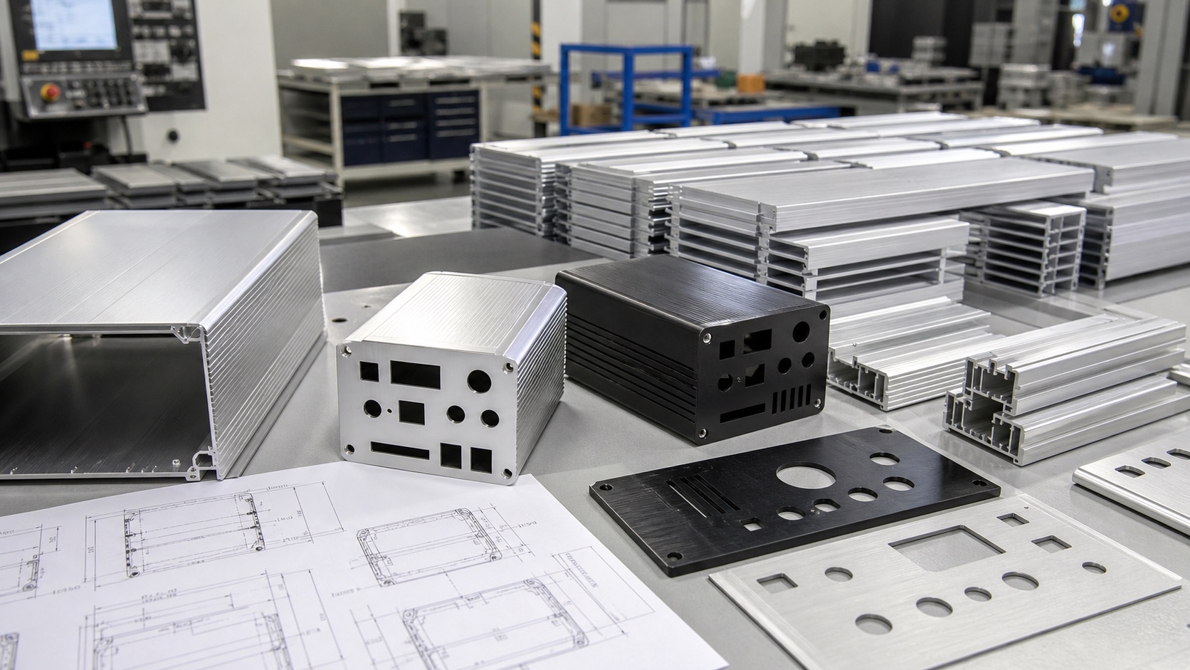
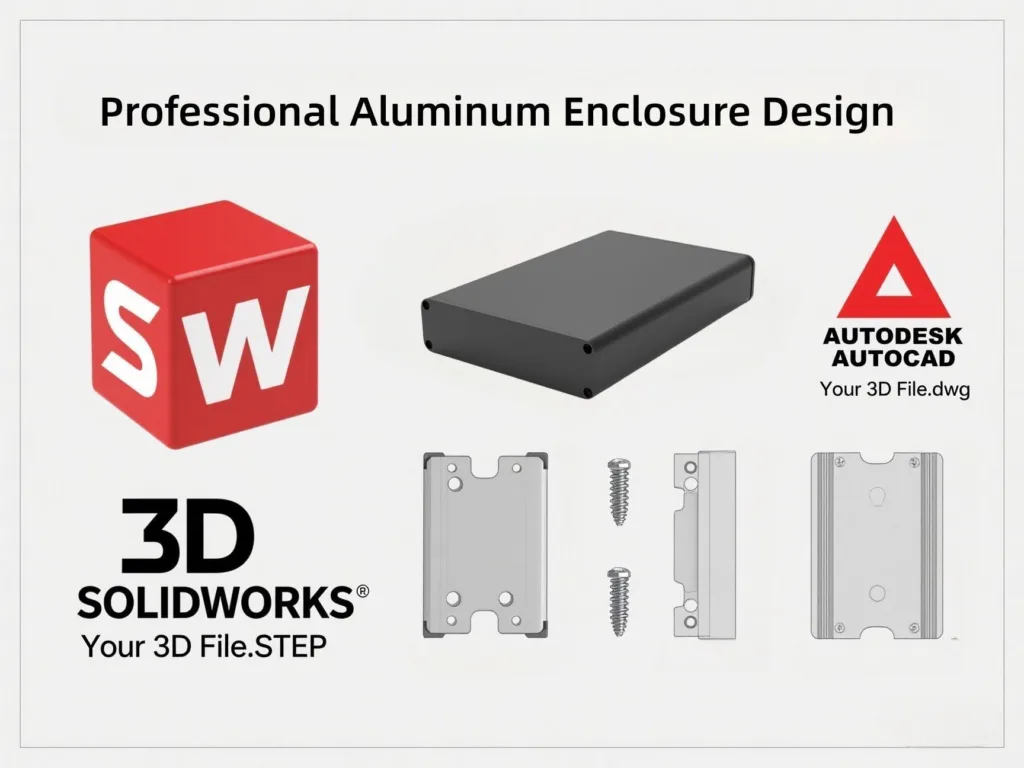
This is also why I like to review 2D drawings together with 3D files. The 3D model shows space. The 2D drawing shows tolerance. A STEP file alone may not tell the CNC operator which dimension is critical. A drawing alone may not show whether the connector body hits the PCB.
For connector-heavy projects, CNC aluminum enclosure machining should start with the end plate or front panel. These parts often decide whether the electronics can be assembled smoothly. If the connector fit is correct, the rest of the enclosure project usually moves faster.
How Can IP67 Sealing Survive Around Connectors and Service Ports?
Waterproof connectors can still leak when the panel surface is poor. A small burr can break the seal. Good CNC finishing protects the IP rating.
IP67 sealing around connectors needs a flat sealing surface, correct gasket compression, enough wall thickness, controlled anodizing, and clean deburring after CNC machining.
The Connector Is Only One Part of the Seal
Many engineers choose an IP67 connector and assume the enclosure will pass IP67 testing. I understand why this happens. The connector supplier has a rating, and the cable assembly looks strong. But the connector rating does not automatically cover the final enclosure. The final result depends on the connector, the machined panel, the gasket, the torque, and the assembly method.
The IEC 60529 IP Code gives the standard framework for ingress protection. In real production, the enclosure must support that target with practical details. The sealing face must be flat. The hole edge must be clean. The gasket must sit on a continuous surface. The operator must tighten the nut or screws with enough control.
Anodizing is also part of the discussion. Anodized aluminum gives a clean and corrosion-resistant surface, and it is common for outdoor electronics. The Aluminum Association shares useful background on aluminum industry standards. But in enclosure manufacturing, I still need to think about where the connector contacts the panel. If the surface layer is too rough, if the hole has a sharp burr, or if the anodizing builds up on a tight cutout, assembly can become difficult.
| Sealing risk | Common cause | Practical solution |
|---|---|---|
| Gasket leak | Uneven panel face | Keep a flat sealing land around the connector |
| Connector tilt | Hole too large or holes misaligned | Add clear positional tolerance on the drawing |
| Damaged gasket | Burr after CNC machining | Deburr and inspect every connector opening |
| Nut cannot tighten | Connector too close to wall | Add tool clearance in the layout |
| Coating interference | Tight cutout after anodizing | Confirm tolerance after surface treatment |
For outdoor sensors, renewable energy monitors, and edge devices, I also ask how often the service port will be opened. A port used only during production can be placed behind a sealed cover. A port used in the field needs better access and a stronger sealing plan. This is where waterproof aluminum enclosures need both mechanical thinking and assembly thinking.
How Can Teams Shorten Lead Time When Connector Layout Changes?
Late connector changes are common in edge AI and IoT projects. They can delay samples. Modular aluminum enclosure planning keeps changes manageable.
Teams can shorten lead time by using standard extruded bodies, CNC machined end plates, early connector tables, shared 2D drawings, and small-batch sample checks.
Design the Enclosure for Change
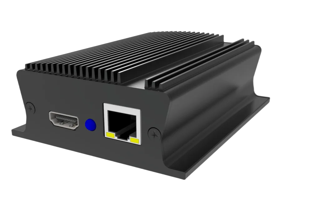
Edge AI and industrial IoT devices are becoming smaller, more powerful, and more connected. The NIST IoT Devices and Infrastructures Group describes IoT systems as combinations of digital, physical, analog, and human components. In enclosure work, I see the same trend in a very practical way. One device may need power input, Ethernet, antenna, sensor ports, USB service access, LED windows, and mounting holes in a compact aluminum case.
This creates a common problem. The electronics team changes the PCB. The customer changes the connector brand. The field team asks for a different cable direction. If the whole enclosure is a one-piece custom CNC housing, every change can be expensive and slow. If the design uses a standard extruded aluminum body with CNC machined end plates, many changes can stay on the end plates. That is usually faster.
At PUMAYCASE, I like this route for prototype and small-batch projects because it protects the schedule. The enclosure body can stay stable. The end plate can change. The anodizing color can stay the same. The logo can be added later by silk screen printing or laser marking.
| Project stage | Enclosure choice | Lead time benefit |
|---|---|---|
| First prototype | Standard extrusion plus CNC end plates | Fast sample with real connector layout |
| Engineering validation | Revised end plates | Lower change cost than a full housing remake |
| Pilot build | Confirmed CNC program and finish | More stable repeatability |
| Small-batch production | Fixed body, controlled panel drawings | Easier quality inspection and assembly |
I also recommend one simple rule. Do not wait until all electronics are perfect before discussing the enclosure. Send the early connector list, PCB outline, heat source position, and mounting direction to the supplier. A good supplier can find risks before machining. For example, I may notice that a cable gland conflicts with a PCB terminal block, or that a connector is too close to a screw boss.
This is the value of custom aluminum enclosure solutions for engineers like Jeff. The goal is not only to make a nice box. The goal is to make a box that fits the PCB, protects the electronics, supports IP needs, manages heat, and can be produced on time. When the project needs fast changes, extruded aluminum enclosures with CNC end plates are often a practical path.
Conclusion
A CNC machined aluminum enclosure connector fit plan helps engineers avoid rework, protect sealing, and keep edge AI and industrial IoT projects moving.