
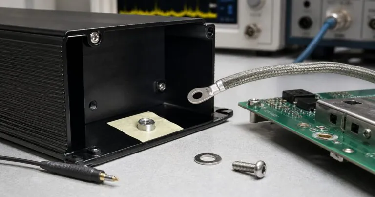
Anodized Aluminum Enclosure Grounding: How Can Engineers Keep EMC Contact?
%anodized aluminum enclosure grounding contact for EMC protection
Anodizing protects aluminum, but it can reduce electrical contact. This can surprise engineers during EMC testing. A clear grounding plan helps an anodized aluminum enclosure work better.
I often see this issue in sealed controllers, gateways, power modules, and industrial instruments. This guide explains how I discuss anodizing, grounding, gaskets, and machining notes with engineers before prototypes.
Table of contents
- 1. Why can anodizing affect grounding?
- 2. Where should engineers keep conductive contact?
- 3. How should EMC, IP sealing, and anodizing be balanced?
- 4. What should be written on the drawing?
- Conclusion
1. Why can anodizing affect grounding?
Anodizing can affect grounding because it converts the aluminum surface into an oxide layer, and that layer is not the same as bare metal contact.
%black anodized aluminum enclosure with masked grounding area
Anodizing is good for many enclosure projects. It improves appearance, corrosion resistance, and wear resistance. The Aluminum Anodizers Council explains that anodizing is an electrochemical process that converts the metal surface into an anodic oxide finish. Their overview of anodizing is a useful technical reference.
The issue is simple. A beautiful anodized surface may not give the grounding path that Jeff expects. If the lid, end plate, PCB ground, and cable shield must connect electrically, the drawing should show where metal contact is required.
| Surface Area | Usual Goal | EMC Concern |
|---|---|---|
| Outside shell | Appearance and corrosion resistance | Usually fine to anodize |
| Lid joint | Sealing and mechanical contact | May need conductive path |
| PCB ground point | Electrical connection | Often needs bare metal or hardware |
| Connector panel | Shield continuity | May need masking or washer contact |
| Screw area | Mechanical clamping | Can support grounding if designed |
Anodizing needs a grounding plan.True
This is true because the finish can change electrical contact even when the mechanical fit looks correct.
2. Where should engineers keep conductive contact?
Engineers should keep conductive contact at selected screw bosses, PCB grounding points, connector shield locations, or lid contact areas when EMC continuity is required.
%custom aluminum enclosure with internal grounding boss and PCB contact point
I do not suggest removing anodizing everywhere. That would reduce the value of the finish. I prefer selective contact. The design can use a masked area, machined contact land, serrated washer, conductive gasket, or grounding screw.
For wireless or noisy electronics, the FCC OET Knowledge Database is useful because it shows how equipment authorization guidance and measurement procedures support compliance work. The enclosure design should not be an afterthought in that process. When a project needs both finish quality and conductivity, I prefer to review custom aluminum enclosure solutions before the first sample.
| EMC Need | Practical Enclosure Choice | Note |
|---|---|---|
| PCB ground | Bare contact boss | Mark it clearly on drawing |
| Shielded connector | Conductive washer contact | Confirm connector datasheet |
| Lid continuity | Conductive gasket or contact pads | Keep sealing path stable |
| Cable shield | Ground near cable entry | Avoid long uncontrolled routes |
| Service repair | Repeatable screw contact | Avoid hidden manual steps |
Selective contact is better than guessing.True
This is true because it protects finish quality while giving the electrical path a clear location.
3. How should EMC, IP sealing, and anodizing be balanced?
EMC, IP sealing, and anodizing should be balanced by separating the seal path from the grounding path, then defining both paths in the enclosure drawing.
%IP67 anodized aluminum enclosure with gasket path and EMC grounding path
A waterproof enclosure needs gasket compression. An EMC-sensitive enclosure needs conductive continuity. A durable outdoor enclosure often needs anodizing. These requirements can work together, but the design must be clear.
For waterproof aluminum enclosures, I first check where the gasket sits. Then I check where the grounding contact should be. If those two paths fight each other, the engineer may need a different groove, screw position, or grounding hardware.
| Requirement | Risk | Practical Solution |
|---|---|---|
| IP67 seal | Conductive contact breaks gasket compression | Keep seal path continuous |
| EMC contact | Anodizing blocks continuity | Mask or machine contact points |
| Corrosion resistance | Bare area oxidizes over time | Place contact inside protected area |
| Assembly speed | Worker misses grounding step | Use obvious hardware and notes |
Seal path and ground path should be reviewed together.True
This is true because one design change can improve one requirement and hurt the other.
4. What should be written on the drawing?
The drawing should state anodizing color, finish type, masked areas, grounding contact points, inspection dimensions, and any conductive gasket requirement.
%engineering drawing notes for anodized custom aluminum enclosure grounding
I like simple notes. For example: black anodized outside and inside, no anodizing on marked grounding boss, laser mark as artwork file, remove burrs around connector holes. These notes are easier to follow than long unclear emails.
The Aluminum Association explains that aluminum standards cover alloy and product systems, including aluminum alloy designation work. Their aluminum standards page is a helpful reference when engineers want to understand why alloy and temper notes matter.
Drawing notes prevent repeat mistakes.True
This is true because the supplier, machinist, anodizer, and inspector all need the same instruction.
Conclusion
An anodized aluminum enclosure can still support EMC contact when engineers define grounding points early. I prefer to plan anodizing, masking, CNC details, and assembly together.