
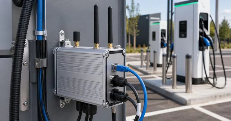
EV Charger Communication Gateway Aluminum Enclosure: How Should Engineers Plan Antennas and IP Protection?
EV charger gateways need stable signals, but metal housings and outdoor sealing can create failures. A custom plan can protect the electronics and keep communication reliable.
An EV charger communication gateway aluminum enclosure should plan antenna position, CNC connector holes, gasket sealing, grounding, and heat paths together. This helps engineers protect OCPP communication hardware, reduce outdoor failures, and shorten prototype changes.
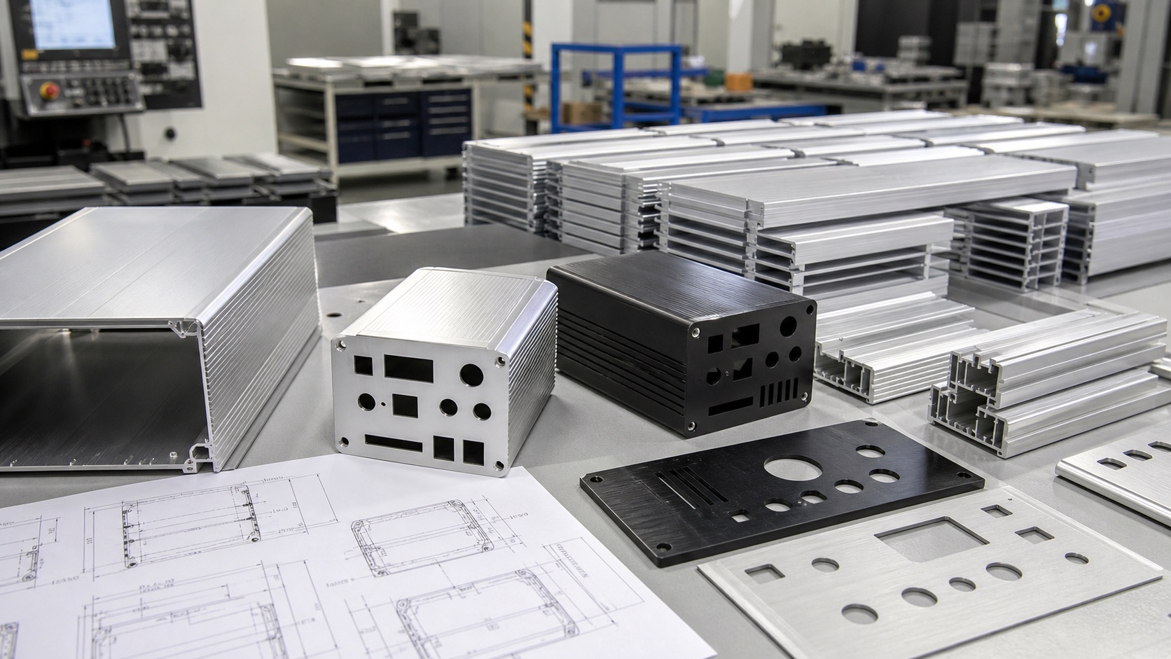
I see more charging projects ask for compact gateway boxes, payment modules, smart charge controllers, and outdoor communication units. These devices look small, but the enclosure decision is not small. A wrong antenna hole or sealing surface can delay the whole charger project. So I want to explain how I usually review this type of aluminum enclosure with engineers before CNC machining starts.
How Should Antenna Layout Work In An EV Charger Communication Gateway Aluminum Enclosure?
Wireless modules need signal space, but aluminum can block RF paths. Poor antenna placement causes weak data links. Engineers should plan antenna exits before finalizing the housing.
Antenna layout in an aluminum enclosure should use external antenna connectors, plastic RF windows, or separated antenna zones. Engineers should keep antennas away from noisy power areas and confirm enough spacing for assembly tools.
Why I Review Antenna Positions Early
I do not treat antenna holes as simple round holes. In an EV charger communication gateway, the antenna layout affects RF signal, waterproof sealing, assembly labor, and future maintenance. Many projects use LTE, Wi-Fi, Bluetooth, GNSS, or sub-GHz modules. Some also use Ethernet, RS485, CAN, or power terminals on the same end plate. If the end plate becomes crowded, the RF connectors may fit on the drawing but fail during real assembly.
The current EV charging market makes this more important. Smart charge management depends on communication between chargers, vehicles, buildings, fleet systems, and utilities. The U.S. Department of Energy explains that smart charge management needs communication among connected loads. The Open Charge Alliance also shows that OCPP supports communication between charging stations and management systems, with OCPP 2.1 released in 2025 for smarter charging infrastructure. You can read their overview of OCPP communication standards.
For enclosure design, I usually ask Jeff for the antenna type first. A small drawing mistake around SMA, RP-SMA, or N-type connectors can cause a nut clearance problem. If the antenna must rotate after installation, the engineer also needs enough space around the connector.
| Antenna choice | Enclosure impact | Risk if ignored |
|---|---|---|
| External SMA antenna | Needs accurate CNC hole and flat sealing area | Loose connector or water leak |
| Internal antenna | Needs non-metal RF window or plastic end area | Weak signal inside full aluminum body |
| Multiple antennas | Needs spacing and orientation review | Antenna coupling or blocked assembly |
| GNSS antenna | Needs sky-facing position | Poor location accuracy |
For PUMAYCASE projects, I prefer to review the PCB, antenna connector datasheet, and 3D model together. This helps my team plan CNC aluminum enclosure machining with fewer changes. It also helps us mark which holes need tight tolerance and which holes only need simple clearance. That small step can save several days during prototype approval.
How Can Engineers Keep IP67 Protection Around RF Connectors?
Outdoor gateways face rain, dust, and temperature cycling. One weak connector seal can damage the PCB. Engineers should design each RF opening as a sealing system.
IP67 protection around RF connectors needs a flat sealing surface, correct connector hardware, gasket compression, and controlled CNC tolerances. Engineers should also test the assembled enclosure, not only the empty housing.
The Connector Is Part Of The Waterproof Design
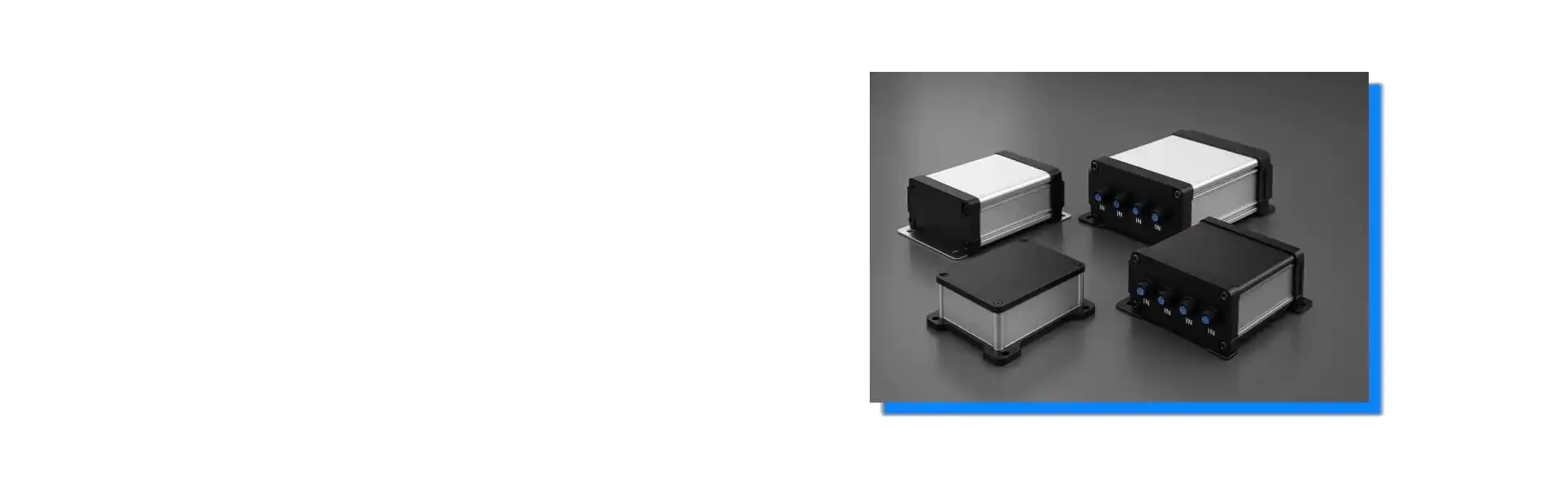
Many engineers ask me whether an aluminum enclosure can reach IP67 or IP68 after adding antenna connectors. My answer is yes, but only if the connector area is designed correctly. The enclosure body, end plate, gasket, screw torque, cable gland, and RF connector all work together. If one part is weak, the rating becomes only a hope.
The official IEC 60529 standard defines the IP Code for degrees of protection provided by enclosures. The IEC page for IEC 60529 is a useful reference when teams discuss IP ratings. But engineers should remember one practical point. The final IP result depends on the full assembly. A bare enclosure and a fully wired gateway are not the same product.
In my work, I check four areas before cutting the end plate. First, the connector flange or washer must sit on a flat surface. Second, the aluminum wall thickness must match the connector thread and nut. Third, the hole tolerance must not damage the sealing washer. Fourth, the connector should not sit too close to the enclosure corner or screw boss.
| Sealing detail | What I check | Why it matters |
|---|---|---|
| Flat washer area | Enough diameter around the RF hole | Washer needs full contact |
| Wall thickness | Thread engagement and nut clearance | Loose hardware causes leaks |
| End plate gasket | Compression after all holes are machined | Openings can weaken the plate |
| Cable direction | Drip path and bending radius | Water should not sit against the seal |
For waterproof aluminum enclosures, I also ask if the device will be mounted vertically, horizontally, or inside a charger cabinet. The same connector may perform differently when rain hits from the top or when condensation forms inside the charger. If the gateway uses several RF and cable connectors, we may suggest a larger end plate or a different layout. This is not to make the box bigger. It is to make the sealing reliable.
How Can Thermal And EMC Needs Stay Under Control?
Gateways often run inside sealed charger cabinets. Heat and electromagnetic noise can reduce reliability. Aluminum enclosures can help when the heat path and grounding points are planned.
Thermal and EMC needs stay under control when the aluminum enclosure acts as a heat spreader and shield. Engineers should connect hot components to the housing and define clean grounding contact areas.
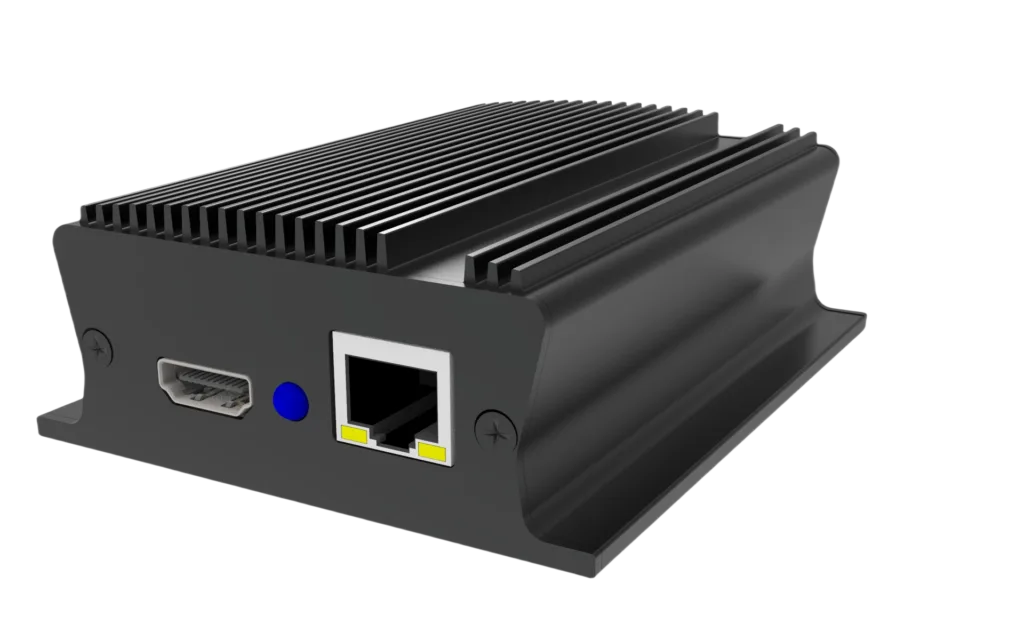
Heat, Grounding, And Service Access Must Work Together
An EV charger communication gateway is often small, but it may contain a processor, cellular module, power conversion, isolation parts, terminal blocks, and several communication ports. If the enclosure is sealed, heat cannot leave through open airflow. The aluminum body must help move heat from the PCB to the outside surface.
I often suggest an extruded aluminum body when the project needs better heat spreading. Extrusion can provide internal PCB slots, external fins, and a strong structure without expensive full CNC machining. For more complex boards, we can add a machined boss, thermal pad contact area, or custom end plate. This is why extruded aluminum enclosures are useful for gateway projects that need both speed and customization.
Wireless reliability is also part of the discussion. NIST explains that industrial wireless systems must deal with reliability, latency, interference, and harsh radio environments. Their page about industrial wireless systems is a helpful reminder that communication products should not be designed like simple indoor boxes.
| Design target | Aluminum enclosure support | Practical note |
|---|---|---|
| Heat dissipation | Body works as heat spreader | Add thermal pad contact to hot chips |
| EMC shielding | Metal shell reduces noise leakage | Keep coating away from grounding points |
| Service access | Removable end plates support repair | Avoid hidden screws under labels |
| Lead time | Standard extrusion reduces tooling delay | CNC only the custom areas |
One common mistake is anodizing every contact area without thinking about grounding. Anodizing is good for corrosion resistance and appearance, but it is not the same as bare metal contact. If Jeff needs reliable grounding, we should define grounding pads, masking areas, or screw contact points in the drawing.
I also like to separate production needs from prototype needs. In the prototype stage, the engineer may change antenna position or connector type. In this case, a custom aluminum enclosure solution based on standard extrusion can be faster than a full new housing. For pilot production, we can lock the end plate drawing, surface finish, laser marking, and assembly process. This makes lead time more stable and reduces supplier rework.
Conclusion
An EV charger communication gateway aluminum enclosure should balance antenna layout, IP sealing, heat, EMC, and lead time before CNC machining begins.