

An industrial controller or measurement device can fit inside a box and still be difficult to install, service, or validate. Connector access, mounting loads, the surrounding environment, and heat-producing components all create requirements for the enclosure. If those requirements arrive after the PCB and interface layout are fixed, a seemingly simple mechanical part can become a major redesign task.
Industrial equipment enclosures provide the physical structure around electronics and the interfaces through which the product is installed and used. Their value depends on how well the enclosure design addresses the actual application and how the complete configuration is verified. For an electronics OEM, the right starting point is a requirements review, not an assumption that any metal box guarantees cooling, sealing, safety, or electromagnetic compatibility.
What Role Does the Enclosure Play in an Industrial Electronic Product?
The enclosure locates and supports components, presents the product's external interfaces, and forms part of its protection strategy. It needs to work with the PCB, connectors, mounting hardware, and customer installation rather than being selected only by external dimensions.
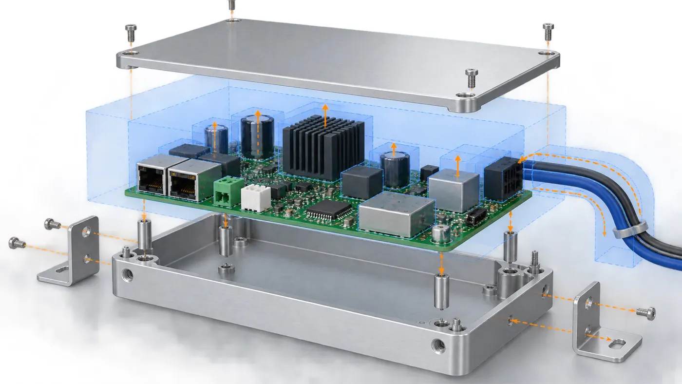
Concept illustration: define the complete product envelope before choosing an enclosure.
- Establish mechanical interfaces. Identify how the PCB, end panels, display, and installation brackets relate to one another. The enclosure must provide usable space for these features and the customer's assembly operations.
- Define access and handling. Consider where cables enter, which controls operators use, and how service personnel reach the device. A connector that fits an opening may still be inaccessible beside a machine wall.
- Connect protection to the installation. A module inside a protected control cabinet and an exposed field instrument face different conditions. Do not assign the same sealing or finish requirements solely because both are industrial products.
- Allocate verification responsibilities. Enclosure-part inspection and complete-device validation answer different questions. PUMAYCASE supplies custom enclosures; the customer installs its electronics and validates its finished equipment.
Statement: An enclosure that fits the bare PCB necessarily fits the complete electronic product.
Answer: False
Explanation: Component heights, connectors, fasteners, cable access, and installation space also affect fit. Review the complete envelope and assembly sequence.
Which Requirements Should Be Defined Before Comparing Options?
Prepare a compact specification that describes the electronics, installation, exposure, and acceptance criteria. This gives suppliers a consistent basis for recommending a structure and identifying information still needed for a quotation.
| Requirement area | Information to prepare | Decision it supports |
|---|---|---|
| Internal envelope | PCB dimensions, mounting features, component heights, and keep-out areas | Whether the proposed internal structure is usable |
| External interfaces | Connector models, openings, display area, controls, and cable access | Panel layout and machining feasibility |
| Installation | Mounting method, available space, orientation, and service access | Suitable structure and attachment features |
| Environment | Intended temperature range, moisture, dust, cleaning, and other relevant exposure | Protection and finish review |
| Functional interfaces | Heat sources and any required electrical contact or isolation locations | Coordination with the customer's thermal and electrical design |
| Supply and acceptance | Quantities by version, appearance references, drawing revision, and sample checks | Comparable quotations and controlled approval |
- Separate requirements from preferences. An essential connector position is different from a preferred color. Identifying which constraints are fixed helps the supplier evaluate available structures without silently changing the product design.
- Describe the actual setting. "Industrial use" does not specify whether the device is in a cabinet, beside moving equipment, or outdoors. Supply the conditions that affect the enclosure decision.
- Identify unresolved assumptions. Mark interfaces still under development. A sample made before those decisions are settled may support a limited review, but should not automatically authorize production.
Statement: The phrase "industrial grade" is a complete enclosure specification.
Answer: False
Explanation: It does not define geometry, exposure, interfaces, or acceptance criteria. Those requirements must be made explicit for the project.
When Can an Existing Aluminum Enclosure Be a Suitable Starting Point?
Evaluate an existing profile or standard enclosure when its basic geometry and structure fit the requirements. Custom machining can adapt compatible features, but it cannot make every dimension or internal detail independently adjustable.
| Enclosure route | Suitable starting conditions | Important limitation |
|---|---|---|
| Extruded aluminum body | The available cross-section accommodates the electronics and the required length is feasible | Changing width, height, wall layout, or internal grooves may require another profile or tooling |
| Assembled instrument enclosure | Separate panels and a frame suit the interface layout and service approach | Panel sizes and joining details depend on the selected construction |
| Rackmount chassis | The equipment is intended for a defined rack installation | Check the actual rack interface, available depth, support, and equipment layout |
| Die-cast or CNC-machined housing | The required geometry is better served by the selected casting or machining route | Tooling, machining access, finish, and quantity must be evaluated for that route |
- Match the fixed geometry first. Check the usable internal envelope and structural features before discussing colors or logos. A compatible starting point can avoid unnecessary redesign of the enclosure itself.
- Confirm each adaptation. Ask which lengths, openings, holes, and mounting features can be customized in the selected product. Do not assume that an existing profile permits arbitrary cross-section changes.
- Compare a dedicated route when necessary. If a critical interface cannot be accommodated, evaluate another structure, new tooling, or a different manufacturing route. Reusing a standard design is useful only when the resulting part meets the requirements.
Statement: Existing-profile customization is always faster and cheaper than a dedicated enclosure.
Answer: False
Explanation: Its suitability depends on fit, machining, availability, finishing, quantities, and approval needs. Compare feasible routes for the specific project.
How Should Protection and Thermal Requirements Be Evaluated?
Evaluate the assembled configuration and its operating conditions. Aluminum can be part of a thermal or electrical design, but the material alone does not establish the performance of an enclosure with covers, openings, connectors, and installed electronics.
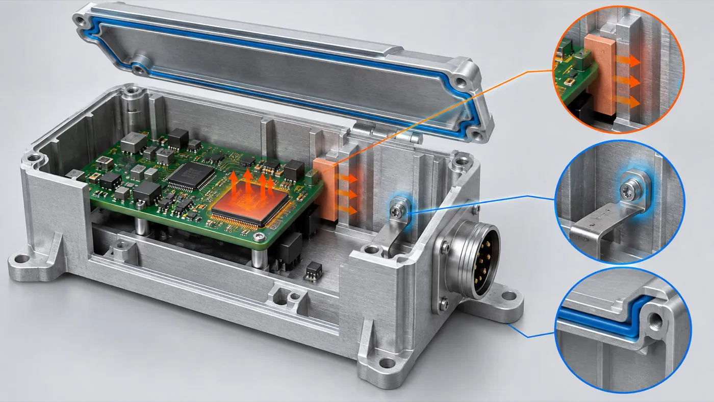
Concept illustration: interface locations require engineering review; the diagram does not demonstrate tested performance.
- Define ingress requirements explicitly. IEC 60529 classifies degrees of protection provided by enclosures using the IP Code. A target rating should be tied to a defined configuration and suitable verification; a "waterproof" product name is not test evidence. [1]
- Review the heat path. Identify heat sources, their interface to any heat spreader or housing, and the surroundings that receive the heat. TI's thermal-design guidance treats interfaces, heat-sink geometry, ambient conditions, and airflow as design considerations. Validate the intended device arrangement. [2]
- Coordinate electrical interfaces. Ask the customer's electrical team to identify required contact, isolation, or grounding features. Openings, joints, finishes, and cable connections need consideration before assuming useful shielding or safe electrical behavior.
- Check competing requirements. A ventilation opening may help one cooling concept while conflicting with a sealing target. Resolve such tradeoffs at the system level before approving machining.
Statement: Adding a gasket proves that a complete electronic product meets its intended ingress-protection target.
Answer: False
Explanation: Covers, openings, connector interfaces, and assembly conditions also matter. Verification must address the defined complete configuration.
What Should Be Specified for Finish, Marking, and Service Access?
Specify appearance together with functional surfaces and the way the product will be used. A finish sample can establish an appearance reference, while drawings identify where coatings, text, or openings could affect installation or maintenance.
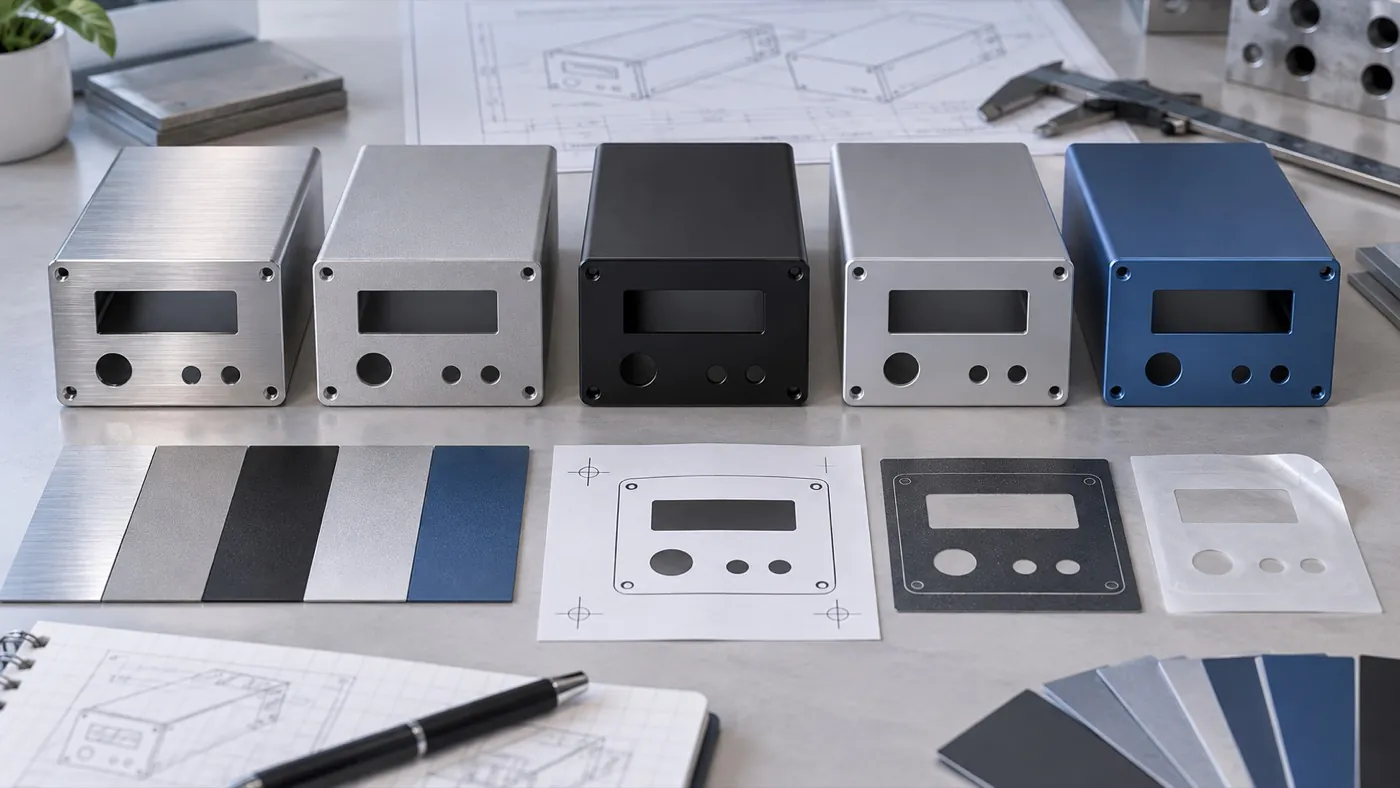
Concept illustration: approve the finish and marking requirements for the intended part.
- Define visible surfaces. Identify the exterior faces, color reference, texture, and appearance acceptance conditions. The appropriate combination of brushing, blasting, anodizing, or powder coating depends on the material and project.
- Identify constrained surfaces. Flag threads, mating interfaces, and any areas with electrical or thermal requirements. Confirm how their finished condition will be controlled rather than treating the exterior finish as the only requirement.
- Control artwork. Provide the approved file for logos, connector labels, and operating legends, including placement and orientation. Screen printing and laser marking should be evaluated against the selected finish and identification needs.
- Review service operations. Check that fasteners and removable panels remain accessible in the intended installation. Features that help the customer assemble or service its device do not mean PUMAYCASE provides assembly services.
Statement: Marking orientation should be checked in the intended installation position.
Answer: True
Explanation: A correctly printed panel can still be difficult to use if its labels face away from the operator or conflict with the installed connector arrangement.
What Should a Sample Demonstrate Before Production Approval?
Use the sample to answer the specific questions that remain open. Record whether it represents the intended machining, finish, markings, and supplied configuration so that a limited fit model is not mistaken for complete production approval.
| Sample check | Evidence to record |
|---|---|
| Customer assembly fit | PCB clearance, mounting access, connectors, and panel alignment |
| Installation fit | Attachment points, surrounding space, cable routing, and service access |
| Appearance and identification | Approved finish reference, artwork, and visible-surface observations |
| Functional validation | Customer test configuration, relevant operating conditions, and acceptance results |
| Production release | Accepted drawing revision, remaining actions, and approval responsibility |
- Use representative mating parts. Confirm the PCB and connector versions used during the review. Substituting a different part without recording it can conceal a later fit problem.
- Separate inspection from testing. Checking opening dimensions does not establish thermal, EMC, ingress, or whole-product safety performance. Define the additional validation required by the customer's application.
- Close changes before repeat supply. Update drawings and artwork when the sample review identifies a necessary change. Record which approved sample represents each configuration.
How Can the Enclosure Specification Support Repeat Orders?
Release repeat orders against a controlled configuration rather than a photograph or an informal description. Clear part identities and approved files let engineering and purchasing distinguish a straightforward repeat from a modified product variant.
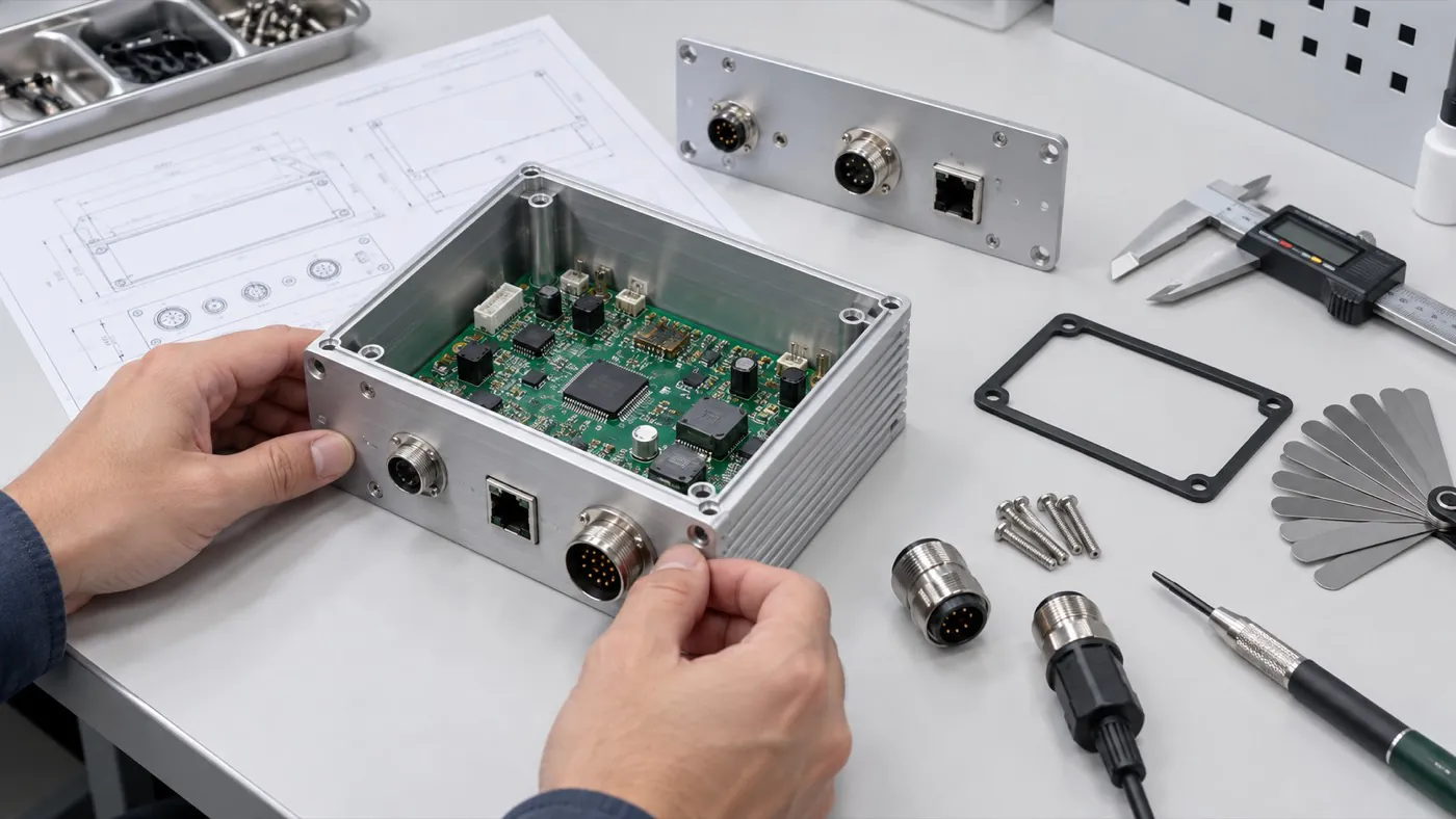
Concept illustration: retain the sample-review record with the released configuration.
- Identify each variant. Keep different lengths, cutouts, finishes, and markings traceable to part numbers or revision records.
- Retain acceptance references. Link the agreed drawing, finish sample, artwork, packaging requirements, and relevant inspection scope to the order.
- Reconfirm changed requirements. A new connector, mounting position, or operating environment may require another fit review or test. A previous approval applies to the configuration actually evaluated.
This documentation helps the supplier understand what to reproduce and helps the customer recognize when a new engineering decision is required.
Conclusion
Industrial equipment enclosures are important because they connect the electronics to the product's installation, handling, and protection requirements. Select the structure using the complete envelope and operating conditions, evaluate existing options where they fit, and verify the configured product before repeat supply. Send PUMAYCASE the PCB envelope, interface drawings, mounting requirements, and target quantities to evaluate an appropriate enclosure and customization route.
References
[1] IEC: IEC 60529 — Degrees of Protection Provided by Enclosures (IP Code).
[2] Texas Instruments: Thermal Design Guide for DSP and ARM Application Processors.