
A PCB can fit inside an enclosure in CAD and still be difficult to install. Connector misalignment, obstructed screw access, or an overlooked component can force changes after machining. For hardware and mechanical engineers developing industrial instruments, reviewing the board and housing together makes these conflicts visible before sample approval.
Coordinate PCB layout and enclosure design by defining the populated board envelope, mounting references, connector access, and operating requirements as one mechanical package. Evaluate an existing aluminum enclosure against that package, identify necessary customization, and validate the finished sample before releasing production drawings.
Which enclosure structure should you evaluate first?
Start with an existing enclosure whose usable geometry and access suit the product. Reusing a suitable profile can avoid developing a new cross-section, but its width, height, internal channels, and assembly direction still constrain the design.
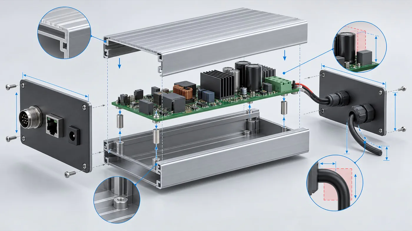
Check the full populated-board envelope before selecting an enclosure structure.
| Structure | Suitable starting requirement | Limitation to review |
|---|---|---|
| One-piece extruded body | A board that can slide into the available section | Insertion clearance and access from the ends |
| Split extruded body | A layout needing access when the body is open | Joint geometry, fastening, and internal support |
| Assembled aluminum chassis | Instruments with multiple panels or boards | Panel interfaces and customer assembly sequence |
| Die-cast or CNC housing | Geometry poorly served by an existing profile | Tooling or machining requirements for the chosen route |
- Check the section first. Compare internal grooves, screw channels, and wall positions with the populated PCB. Outside dimensions alone cannot establish fit.
- Identify flexible dimensions. Length may be adjustable for a selected extrusion, while changing its cross-section can require another profile or tooling. Confirm the permitted modifications for the actual model.
- Compare manufacturing routes. Extrusion followed by cutting and machining differs from casting or machining a body from stock. Evaluate the route around the geometry and expected supply requirements.
PUMAYCASE can evaluate existing aluminum enclosure solutions before a dedicated route. An existing design does not imply that every model is in stock or that reuse is always faster or less expensive.
Statement: An existing extrusion profile allows every enclosure dimension to change without new tooling.
Answer: False
Explanation: Its cross-section constrains the design. Changes must be evaluated against the selected profile and manufacturing method.
Which dimensions determine whether the populated PCB will fit?
Define the space occupied by the complete board and everything needed to install it. Include components on both sides, connectors, fasteners, and cable access, then compare that envelope with the usable cavity throughout insertion.
| Information needed | What to include | Why it affects selection |
|---|---|---|
| Board outline | Width, length, thickness, notches | Establishes the basic fit and mounting options |
| Component envelope | Upper and lower component heights | Identifies contact with walls, supports, or covers |
| External connections | Plug bodies, latches, and cable direction | Determines usable access beyond the connector opening |
| Installation path | Board movement and tool clearance | Reveals interference before the board reaches its final position |
- Model the complete board. A bare PCB model can conceal collisions with underside components or connector housings. Mark uncertain component envelopes before selecting a cavity.
- Check the movement. A board may fit at its final location but hit a screw channel during insertion. Review the assembly sequence with the proposed enclosure structure.
- Define necessary clearances. Base allowances on the product's mechanical and electrical requirements. There is no single clearance suitable for every circuit or installation.
Statement: PCB width and length alone are sufficient to confirm enclosure fit.
Answer: False
Explanation: Component heights, support geometry, connectors, and installation access also determine whether the board can be installed and used.
Choose the mounting method before freezing panel openings because it establishes the board position. Dimension the supports and connector openings from agreed reference surfaces, or datums, so the drawings describe the same physical arrangement.
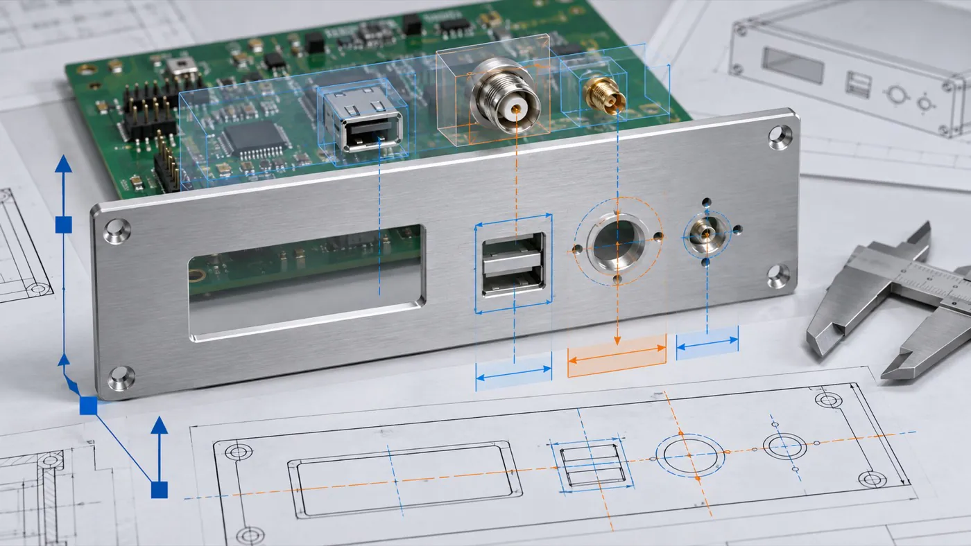
Shared functional references reduce mismatch between PCB mounting and panel openings.
| Mounting method | Main fit check | Access check |
|---|---|---|
| Screws and standoffs | Support height and underside clearance | Screwdriver access and screw length |
| Internal PCB grooves | Board thickness and edge keep-out | Insertion path and end retention |
| Brackets or carrier plate | Added stack height and support locations | Fastener sequence and board removal |
- Use connector documentation. Include the actual part number and panel drawing. Confirm panel thickness limits, mounting hardware, and the space required by the mating plug.
- Trace the locating features. An opening referenced to one panel edge can become inconsistent with a board referenced to another surface. Show how these references relate.
- Check connection loads. Review how plugging and unplugging affects the connector and board. Do not use panel fasteners to pull a misaligned connector into position.
Statement: Changing PCB support height can change connector alignment with the panel.
Answer: True
Explanation: The supports establish board position, so their height must be coordinated with the connector and opening geometry.
Which tolerance checks help prevent panel rework?
Evaluate variation across the features that locate each interface. Board geometry, supports, connector placement, machining, and finishing can all influence assembled fit even when individual parts meet their drawings.
| Functional interface | Features to review together | Acceptance question |
|---|---|---|
| Connector opening | Board supports, connector location, opening position | Can the intended plug mate without interference? |
| PCB retention | Board thickness, grooves, retaining parts | Is the board supported and retained as intended? |
| Panel joint | Mating surfaces, fastening, finish | Does the finished joint close correctly? |
- Mark critical dimensions. Identify features that control fit rather than assigning equally tight limits to every surface. Agree on achievable requirements before machining.
- Specify the finished condition. State whether dimensions apply before or after surface treatment, especially at close-fitting interfaces.
- Review accumulated variation. Check how deviations can combine unfavorably across mating parts. A nominal CAD fit is only the starting point.
- Inspect the interface. Supplement individual measurements with a trial using the intended components. Record any necessary adjustment before approving the drawing revision.
The enclosure tolerance guide covers this interface review in more detail.
Statement: Parts that meet their individual dimensions always fit correctly together.
Answer: False
Explanation: Variation across mating parts can accumulate. The interface must be evaluated as an assembly.
How do heat, electrical contact, and sealing influence the layout?
Reserve space for these functions before fixing the board location. An aluminum body does not by itself demonstrate adequate cooling, EMC performance, or ingress protection; each depends on the complete product design and its validation.
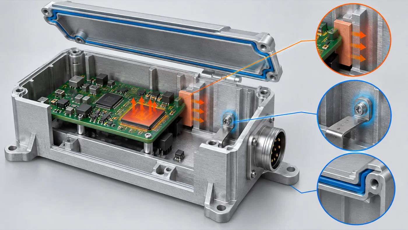
Thermal paths, electrical contact, and sealing interfaces must be evaluated as part of the complete product.
| Requirement | Information to define | Verification needed |
|---|---|---|
| Heat transfer | Heat sources, operating load, interface geometry | Temperatures under representative operation |
| Electrical contact | Intended contact areas and finish requirements | Checks appropriate to the electrical design |
| Ingress protection | Target, openings, seals, and connectors | Evidence covering the intended final configuration |
- Define the heat path. Identify how heat reaches the enclosure and leaves it. Select thermal interface geometry and compression using the relevant component and material documentation.
- Specify contact surfaces. Do not assume that a finished surface provides the intended electrical connection. Coordinate contact areas with surface treatment requirements.
- Include every opening. Ventilation, connectors, and service joints belong in the protection review. The IP Code classifies enclosure protection under IEC 60529; it is not a material category. 1
Keep thermal, electrical, and environmental acceptance criteria separate so one successful check is not treated as proof of all three.
Statement: Selecting an aluminum enclosure alone establishes the final device's EMC compliance.
Answer: False
Explanation: Electronics, joints, apertures, cables, and contact arrangements also affect the result. Validate the complete product against its applicable requirements.
What information should engineering send for an enclosure review?
Send one consistent package that connects the PCB, enclosure interfaces, finish, and intended supply scope. Drawings should capture requirements that a model alone does not communicate, including threads, critical dimensions, and acceptance criteria.
| Review item | Information to provide |
|---|---|
| Geometry | PCB envelope, mounting references, and available models |
| Interfaces | Connector drawings, openings, installation requirements |
| Finish and marking | Process preference, appearance criteria, artwork location |
| Validation | Sample checks and unresolved assumptions |
| Supply | Sample or pilot needs, expected quantities, repeat-order requirements |
- Align revisions. Give matching drawings and models the same release reference, and explain any intentional differences.
- Separate fixed and flexible requirements. This lets the supplier evaluate an existing enclosure without assuming essential product features can change.
- Define responsibility. PUMAYCASE supports enclosure selection, customization, and supply; it does not provide PCB installation, wiring, or assembly services. The customer arranges product assembly and system validation.
Quantity, manufacturing scope, sample requirements, and timing need project-specific confirmation.
How should you approve the sample before repeat orders?
Use the sample to close the open interface questions, then release a controlled set of approved requirements. Approval should refer to the actual enclosure configuration and drawing revision so purchasing can order the same arrangement again.
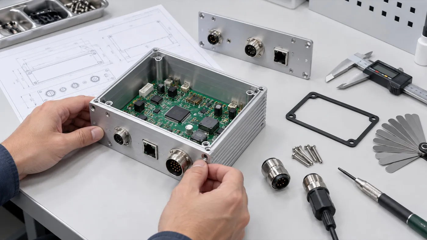
Inspect the actual PCB, mating connectors, hardware, and enclosure sample before release.
- Trial the intended installation. Fit the PCB, fasteners, plugs, and cables using the planned sequence. Record interference or restricted service access.
- Check finish and markings. Compare visible surfaces, label positions, and connector identification against the agreed requirements.
- Close changes before release. Incorporate approved corrections into the drawings and identify which earlier files are superseded.
- Control repeat orders. Reference the approved revision and acceptance criteria; review later component substitutions for possible mechanical effects.
A sample establishes an agreed reference, while production inspection and change control support consistent repeat supply.
Conclusion
PCB layout and enclosure design should be reviewed as connected interfaces: the populated board, supports, connector openings, functional clearances, and operating requirements must work together. Evaluate an existing enclosure where its geometry fits, confirm necessary customization, and validate the sample before releasing repeat orders. Send PUMAYCASE your PCB envelope, interface drawings, mounting requirements, and target quantities to assess a suitable enclosure and customization route.